Final walk through in a couple of hours, closing tomorrow. I don't know how I survived playing with all the cool stuff under the sink as a kid.
Kid? I don't know how I survived it as an adult! Just good job no one will deliver LN2 in small quantities to my house 🙂
@JN: You are using a double bifilar voice coil for the correction, right? So they make a transformer, with inductances of Le (L2 in my circuit) PLUS the gyrator primary voltage, that cannot be separated.
But even if the K1 correction voltage is taken from gyrator input, it still does not help to kill the distortion. Remember, current drive, current is linear, serial elements behind gyrator transform as parallel R//L//C to primary side, R or L or C is non-linear, driving current is linear, but partial current through R or L or C is not.
But even if the K1 correction voltage is taken from gyrator input, it still does not help to kill the distortion. Remember, current drive, current is linear, serial elements behind gyrator transform as parallel R//L//C to primary side, R or L or C is non-linear, driving current is linear, but partial current through R or L or C is not.
The voltage across L2 is supposed to be the exact same voltage as the primary of the transformer.
Is it in your model?
The non linearities you have tacked into the right side, they are in series with the inductance of the voice coil. So, as frequency goes up, the non linearities decouple.
But the L2 inductance is the cause of the non linearities, not in series with them.
I suspect your model is insufficient for the task. Nice work, I am glad to look at it, but my thinking is that because this coupled coupled yada yada stuff is two weeks in the making, the models are not there yet.
Actual measurements, different story..
jn
I'm pretty sure if you wound the wire back on a mandrel and glued it again, then to the dome, you would have a perfectly good functioning tweeter once more.
That sounds like cooking a box of angel hair pasta, and then trying to put it back in the box in an orderly fashion with one hand tied behind your back, on a motorcycle riding down railroad tracks..with wild hyenas nipping at your shoes..
You know, kinda like a typical work environment..
jn
I think this presentation clearly shows what can be done in distortion reduction by servo control, current drive and other means
http://cogsys.imm.dtu.dk/nonlincomp/Klippel.pdf
Active Compensation of Transducer Nonlinearities
W. Klippel
KLIPPEL GmbH, Dresden, Germany
Symposium
Nonlinear Compensation of Loudspeakers
Technical University of Denmark, 2003
http://cogsys.imm.dtu.dk/nonlincomp/Klippel.pdf
Active Compensation of Transducer Nonlinearities
W. Klippel
KLIPPEL GmbH, Dresden, Germany
Symposium
Nonlinear Compensation of Loudspeakers
Technical University of Denmark, 2003
The voltage across L2 is supposed to be the exact same voltage as the primary of the transformer.
Is it in your model?
The non linearities you have tacked into the right side, they are in series with the inductance of the voice coil. So, as frequency goes up, the non linearities decouple.
Yes, the voltage across L2 (which inevitably includes the gyrator primary voltage or call it EMF if you want).
The non-linearities plus mass, friction and compliance are connected to common velocity and transfer as a parallel circuit connected in series with voice coil on electrical side.
The speaker model used is a standard model used in electroacoustics theory, textbooks and the one that Klippel uses as well. It is the basics of electroacoustics. You can make its elements non-linear, if needed.
Attachments
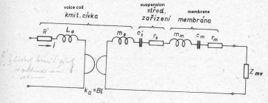
Yes, the voltage across L2 (which inevitably includes the gyrator primary voltage or call it EMF if you want).
The non-linearities plus mass, friction and compliance are connected to common velocity and transfer as a parallel circuit connected in series with voice coil on electrical side.
The speaker model used is a standard model used in electroacoustics theory, textbooks and the one that Klippel uses as well. It is the basics of electroacoustics. You can make its elements non-linear, if needed.
My concern is to try and keep the model as simple as needed, but no simpler.
I am not confident that your model matches reality. It could be that I just need to learn the model better, or it could be that it is overly complex and missing stuff..
Oh, BTW. The fact that a "standard model" is embraced does not necessarily mean it is entirely accurate, only that it has produced results consistent with theory. You are trying to shoehorn a standard model to fit the magnetic analysis I have created, and it's not clear at all that it is a good fit yet.
So, you are stating that my feedback design will NOT reduce harmonics below that of a standard voltage drive?
Again, thank you for your efforts..
jn
Last edited:
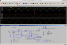
Here is my simulation with Bl(x), Bl(I), Le(x) and Le(I) nonlinearities added which I can turn on and off with parameters. I tried to match the distortions to this paper:
https://www.almainternational.org/y...ses_in_microspeakers_alma_2013-1.10691701.pdf
But it seems Klippel included time-dependent behaviors in Le(x) and Bl(x) (no mention of Bl(I) or Le(I)) which I haven't tried to model without a good hint at their functions. The distortions in my model still always decrease with frequency. I added a abs(d(x)) term to the Le(I) function, but distortion still doesn't rise with frequency.
Should I just keep expanding the model using empty nonlinear functions to be filled in later? I haven't included mechanical nonlinearities yet, but I can, even better if someone can give me their functions in a way I can plug into the simulator.
Attachments
Regarding a suitable driver for current drive, ol' Thorsten talked about this back in ... 2004! (God I'm getting old!)
...PS, driving moving coil speakers designed to require external electrical damping will not work of course, we must in effect design drivers with a Qm in the region of 0.3 to 1 as the only possible damping is mechanical.
A good choice would be a seamless Aluminum coil former, this would both kill some of the eddy current problems in the polepieces and reduce the drivers voicecoil inductance drastically and it would give inherent damping to the driver that would in effect appear as very low Qm. Of course, such a speaker when driven from a normal amp would have absolutely no bass...
https://www.diyaudio.com/forums/mul...rs-tranconductance-amplifiers.html#post127252
...Having experimented with similar configurations (using chipamps) in the mid 80's of the last century I can attest to the rather surprising transformation of the sound. I ended up using current drive only on wideband midranges and tweeters (so from around 200Hz upwarsd), ending up with negative feedback via electret mike capsulas for the woofers (this was a fully active 3-Way speaker).
IF and that is a BIG IF I could design my "dream" Speaker driver from scratch I suspect it would look like this:
1) Fieldcoil Magnet with constant current actuation
2) Linear Magnet Field Geometry (Similar to JBL's SFG style arrangement)
3) Qm of the woofer cone section controlled by electromagnetic breaking (eddy current in the aluminum voicecoil former) and a voicecoil winding that makes the Qm the woofers dominant Q, not as usal Qe.
4) Coincident (in the same magnet gap) ICT style 2" Tweeter Dome, induction from the Woofer voicecoil coupled to the tweeter dome acting in effect as transformer to drive a very low resistance "voicecoil". The tweeter requires a form of phaseplug to extend the treble past 10KHz by avoiding cancellation, maybe a ring radiator arrangement would be good.
The above driver would be technically speaking "full-range" (or rather wideband) without electrical crossover as such, fully phase/impulse coherent. I'd probably aim at around 105db/2.83V/1m with a range covered of around 125Hz-12.5KHz, meaning it would likely have to be a 12 - 15" unit.
Together with that it would be nice to have a 20" or larger Subwoofer driver similar in constrction to the above and of course to drive the speaker drivers actively with "current drive" on open baffles. Add a nice ceramic or ribbon supertweeter....
Well, we all can dream.
Sayonara ...
https://www.diyaudio.com/forums/mul...-tranconductance-amplifiers-2.html#post127780
Some good discussion in that thread on v vs i drive, magnetic considerations and mechanical dampening by thorsten, nelson, steve eddy, jan, GM, ...
Ah the gud ol' days!
Cheers,
Jeff
Last edited:
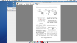
This paper gives some good hints in figure 6:
https://hal.archives-ouvertes.fr/hal-01103598/document
https://hal.archives-ouvertes.fr/hal-01103598/document
NaOH is a no-go; FWIW, it attacks a lot of things that you certainly wouldn't want it to (organics). Same with KOH. Your classic "Piranha" etch (3:1-5:1 conc H2SO4:H2O2; 30% commercially pure H2O2, aka "nasty stuff"), with etch aluminum fairly well, and preferentially to copper, BUT there won't be an organic left in sight afterwards.
There might be a couple chemistries for etching aluminum that don't cause passivation that don't attack the enamel, but they're not going to be obvious. (and I don't know them off the top of my head.
There might be a couple chemistries for etching aluminum that don't cause passivation that don't attack the enamel, but they're not going to be obvious. (and I don't know them off the top of my head.
Klippel knows their stuff. Let's rely on them! Keantoken's AES reference is great too! Let us study, before we speculate.
Last edited:
Yes, and he is a real professional in speaker design and diagnosis. It is much better to study his documents than to try to reinvent speaker's elementary.
You both sound like that argument about closing the patent office, as everything has already been invented..
Oh, and btw...I have studied them, have gone through quite a bit.
I find voltage driven, current driven, and velocity driven. All three are easy to understand.
But never what I propose.
Sometimes a different way of looking at a problem is not well understood.
jn
ps. If you really want to try and do it, you have to push the magnetics, not a complex model such as you are trying.
Get rid of all the gyrator stuff, start with my simple model, but add a 3rd co-wound coil to the 1:1, but drive it with a constant current harmonic source locked to the fundamental. That way, the third coil doesn't load the impedance, but you can inject second and third. You know, the way the speaker magnetics actually work. Worry about Le(x) variation later.
pps. And yes, he is a real professional..
Last edited:
Keantoken, please keep up the good work. Ehm, would you like to share the .asc also?Here is my simulation with Bl(x), Bl(I), Le(x) and Le(I) nonlinearities added which I can turn on and off with parameters. I tried to match the distortions to this paper:
https://www.almainternational.org/y...ses_in_microspeakers_alma_2013-1.10691701.pdf
But it seems Klippel included time-dependent behaviors in Le(x) and Bl(x) (no mention of Bl(I) or Le(I)) which I haven't tried to model without a good hint at their functions. The distortions in my model still always decrease with frequency. I added a abs(d(x)) term to the Le(I) function, but distortion still doesn't rise with frequency.
Should I just keep expanding the model using empty nonlinear functions to be filled in later? I haven't included mechanical nonlinearities yet, but I can, even better if someone can give me their functions in a way I can plug into the simulator.
That Klippel paper again makes clear that the BL(x) nonlinearity is still the major distortion contributor for large signals / high excursion and none of the simpler methods (current drive, including JN's -- degenerated or not; using the VC as velocity sensor; etc) can address it, only the driver design can (either genererously underhung VC or generously overhung with very symmetric magnetics)... or a true independent sensor MFB (still with some means to soft-limit the excursion...
Looks like it refers to an *independent* velocity pickup coil to me, not a DVC where one coil is used as sensor but suffers from the coupling. The accompaning text to that figure should give indication.Doesn't the circuit on the right look familiar? What am I missing?
I have not seen Klippel give the equations for the reluctance force that is given in that paper.
We already did that a few pages ago didn't we? This has been pretty well established. Designing the circuit isn't the problem either, it's ready for prototype as far as I'm concerned. So how much later are you talking about? What have we not done that we need to do before that?
The harmonics injected in the 3rd coil will present equally in both voicecoils. They will cancel at the feedback point. The residual will depend on the amount of feedback, unless we deliberately mismatch the coils. But then the residual will just be the nonlinearity scaled down, this doesn't give us anything we don't already know.
Get rid of all the gyrator stuff, start with my simple model, but add a 3rd co-wound coil to the 1:1, but drive it with a constant current harmonic source locked to the fundamental. That way, the third coil doesn't load the impedance, but you can inject second and third. You know, the way the speaker magnetics actually work. Worry about Le(x) variation later.
We already did that a few pages ago didn't we? This has been pretty well established. Designing the circuit isn't the problem either, it's ready for prototype as far as I'm concerned. So how much later are you talking about? What have we not done that we need to do before that?
The harmonics injected in the 3rd coil will present equally in both voicecoils. They will cancel at the feedback point. The residual will depend on the amount of feedback, unless we deliberately mismatch the coils. But then the residual will just be the nonlinearity scaled down, this doesn't give us anything we don't already know.
. It is much better to study his documents than to try to reinvent speaker's elementary.
Well I think studying his documents and then try and invent NEW ways of doing speakers is a worthy use of some time. Always worth seeing if another field has some information that the speaker people had missed. Even if it ends up as a gnatfart improvement its been tried, rather than just being talked about. WNTL?
Oh and when did JC become the peanut gallery?
Doesn't the circuit on the right look familiar? What am I missing?
In this case we are rejecting Re and driving the EMF component with voltage drive. In jneutron's circuit we are rejecting the EMF component and driving Re with voltage drive.
- Status
- Not open for further replies.
- Home
- Member Areas
- The Lounge
- John Curl's Blowtorch preamplifier part III