Actually, I am working sixth order negative feedback servo's where due to non linearities, the phase margin changes with position. This requires adaptive tuning of gain, integral, multiple feed forward terms, as well as lead screw compensation and backlash compensation.Now, what about really fancy servo systems? Nope, I didn't design them, but JN, I doubt that you have either.
What I am doing if far beyond your level of experience, it would take weeks to bring you up to speed. I believe you can understand this stuff, but you've no experience nor insight into what I'm doing. Much of it is the digital domain, DSP stuff and all, but the electronics and mechanics is definitely analog.
Lies do not become you. The fact that someone else did not understand my post does not mean I didn't. If you want to be taken seriously, you need to actually get serious. That same person mis-identified a voltage controlled loop, yet I did not accuse him of anything other than simple misidentification, I know he understands.You simply did not recognize the basic circuit for a voltage controlled, current output amplifier that YOU drew up!
50 years, 50 years...It is literally the same basic circuit as I used 50 years ago to drive the automotive window opener motor that we used for the capstan phase locked servo. It worked OK, but much better was possible.
Any chance you could talk about stuff from this century?
Jn
Last edited:
It might be. There are many effects, and once we cancel out what is gross, what is left will be something to discuss.But when the EMFs cancel, how do you know it will not just be a smaller version of the same EMF? After all the coils are designed to have the best coupling and occupy closest to the same physical position as possible. Won't the residual just be the EMF, but divided by 100 or whatever?
I've already been down the rabbit hole of co-winding a pickup coil, in that as proximity effect occurs the current centroid shifts inward (for solenoidal coils). That means that in theory the Le(x) gradient should couple exactly the same, but I cannot guarantee that the centroids are at the same radial position in the wire. So when second harmonic voltage appears in the difference, is it centroid position modulation, or is it resistive proximity effect, or the I dL/dt term attacking the coil current? The third will cancel, first two may not.
Bifilar equal diameter coils sound better(not acoustically but theoretically), but I'm not sure if the centroid of the pickup will mirror the centroid of the drive, giving the same inductive pickup. Even coaxial wire wound coils, the shield currents shift by proximity.. Sometimes you can't win.
Jn
Last edited:
Esa,Here are some of my voltage/current comparison results - ...
it seems atypical that 3rd harmonic distortion increase while 2nd decrease at higher frequency on voltage drive as shown on your link for both woofer and midrange. Did I miss something?
I am learning a lot about magnetics here. Fascinating discussion and some good questions from keantoken. 🙂
The first thing I will measure on the drivers is the matching, by connection the coils in anti-series, hence same current for both (removing Rdc mismatch). If the gross BL is the same for both coils, output should be zero. Hopefully the matching will be 3%/-30dB, with a bit of luck it may reach 1%/-40dB
Looks like you misinterpret the graphs. Execpt for the glitch at 120Hz H3 there is no point in the graphs where voltage drive gives lower distortion than current drive.Esa,
it seems atypical that 3rd harmonic distortion increase while 2nd decrease at higher frequency on voltage drive as shown on your link for both woofer and midrange. Did I miss something?
I mean typical distortion reading on regular voltage drive usually show decreasing H3 going higher in frequency like Pavel's Seas.Looks like you misinterpret the graphs....
Esa's link show increasing H3 with decreasing H2 towards higher frequency for woofer and midrange. Either the drivers are atypical or I miss something like normalization or weighting.
From Distortion example: Vifa | Current-Drive - The Natural Way of Loudspeaker Operation
".... The V/I conversion is thus the most significant source of 3rd harmonic distortion in dynamic drivers and a very significant one also in the 2nd."
Is this something that will be mitigated in the jn-drive?
//
".... The V/I conversion is thus the most significant source of 3rd harmonic distortion in dynamic drivers and a very significant one also in the 2nd."
Is this something that will be mitigated in the jn-drive?
//
I mean typical distortion reading on regular voltage drive usually show decreasing H3 going higher in frequency like Pavel's Seas.
Esa's link show increasing H3 with decreasing H2 towards higher frequency for woofer and midrange. Either the drivers are atypical or I miss something like normalization or weighting.
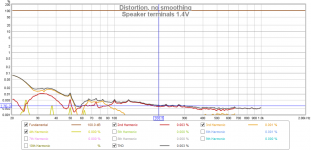
I think it is worthy to display or at least to check distortion at the power amplifier output, with speaker connected. It is good to know that amplifier distortion does not rise with frequency and that the amplifier distortion is always at least 20dB below measured speaker distortion, everywhere, at any frequency and amplitude.
You used one of my measurements as an example and I would like to add a measurement of distortion (voltage) at speaker terminals, behind the speaker cable. This measurement belongs to acoustical measurement that you have shown, but at 1.4V, I am afraid that for 3.2 it has not been saved, however there would not be a big difference.
Attachments
Last edited:
Just recall that I have 10 pcs of 2,2 ohm - 100W resistors lying around - reading Esa's pages I feel I have to hook in say 1 ohm to my speakers and try this. As it happens I'm also experimenting with EQ implemented by my DAC so I can compensate for any FR impact. 400 watt nCore helps.
//
//
A nice test. A bifilar will be closer by design.The first thing I will measure on the drivers is the matching, by connection the coils in anti-series, hence same current for both (removing Rdc mismatch). If the gross BL is the same for both coils, output should be zero. Hopefully the matching will be 3%/-30dB, with a bit of luck it may reach 1%/-40dB
An inner/outer set will have more difference. We have that issue here, as the two layers do not contribute equally, a center tap halfway in the layers will not be center.
Another check would be wire series, and see if the center actually is.
Vs frequency, right?
Jn
Yes, I would try measure near field SPL function with series'd coils, in-phase vs. out-of-phase, voltage drive. Needs a lot of care because the out-of-phase SPL will be tiny.
Could be that S/N is better when measuring pure microphonic terminal voltage from external cone exitation (second driver mounted face-to-face, and first driver unterminated).
Could be that S/N is better when measuring pure microphonic terminal voltage from external cone exitation (second driver mounted face-to-face, and first driver unterminated).
You mean like in a bridge, with equal R divider on the known leg?Another check would be wire series, and see if the center actually is.
This also indicates DCR imbalance which is not relevant for us here, so I would not use that to judge back-EMF matching.
You mean like in a bridge, with equal R divider on the known leg?
This also indicates DCR imbalance which is not relevant for us here, so I would not use that to judge back-EMF matching.
True, but capacitors are our friends.
A dc imbalance would also be relevant as well.
Also, dc could be trimmed at the bridge, then see what the ac does.
We are after all, measuring through litz and 8 solder joints. 40dB below 4 ohms being 40 milliohms.
Jn
Last edited:
Even with DC trimmed out the AC would not match even when BL is the same, just think of your DVC with one coil being much higher resistance. Yer their BL(x,i) in the way it forms the instantaneous multiplier for the velocity voltage, and hence their back-EMF, is the same. This is for use as per your back-EMF cancelling scheme where the DCR of the sense coil is irrelevant.
With both coils current driven and a servoed balanced Birt bridge velocity extractor the matching of BL and parasitics like DCR is relevant, of course (in that case, to free the DC (=temp) output of the bridge from AC as much as possible, by the balancing). Still this might need trimming for optimum results with less than perfectly wound bifilar coils.
With both coils current driven and a servoed balanced Birt bridge velocity extractor the matching of BL and parasitics like DCR is relevant, of course (in that case, to free the DC (=temp) output of the bridge from AC as much as possible, by the balancing). Still this might need trimming for optimum results with less than perfectly wound bifilar coils.
I tried to simulate Re drop subtraction, but the circuit is unstable. No way to cure for me, yet.
My thinking is that if it is seen by the pickup, it can attack it.From Distortion example: Vifa | Current-Drive - The Natural Way of Loudspeaker Operation
".... The V/I conversion is thus the most significant source of 3rd harmonic distortion in dynamic drivers and a very significant one also in the 2nd."
Is this something that will be mitigated in the jn-drive?
//
I am not sure what you are trying to subtract.I tried to simulate Re drop subtraction, but the circuit is unstable. No way to cure for me, yet.
I am goint to put together a bunch of information on what our terminology means so we all speak about the same thing.
I'm not sure where t put it, as it cannot be on this site, unless we can make it a wiki.
Jn
- Status
- Not open for further replies.
- Home
- Member Areas
- The Lounge
- John Curl's Blowtorch preamplifier part III