Ah cool. It just stuck out on a quick scan of the plot. Good to know nothing to worry about.
Always good to remind oneself that speaker distortion is 1000x amplifier distortion 😀
Always good to remind oneself that speaker distortion is 1000x amplifier distortion 😀
But it's a different "kind" of distortion (according to Earl Geddes?) not sure of the explanation of that.....
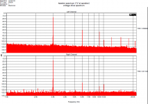
Now with a pure voltage drive, I get almost the same distortion and spectrum as with the current drive. So for this tweeter there is no improvement under current drive. This confirms what I measured years ago, the only notable change was for woofers.
Attachments
The simple explanation is "speakers are bit crap"...
Yes T2030 are, but other tweeters also did not profit from the current drive. T2030 is just the only speaker driver I have "free" and I can use it for the experiment. It was driven directly, no cross-over, and was placed on a rectangular baffle 30 x 45 cm, about 10cm left and top from baffle center.
Of course.When making thoughts about speaker distortion, it should be understood that there is not only one transformation in the speaker, but two. Speaker is an electro-mechanical transducer and also mechano-acoustical transducer. So it is not enough to consider speaker as an electro-mechanical transducer. Mechano-acoustic transformation is also non-linear, covering membrane modes, break-ups, etc. This is probably not expressed in the speaker current or in the second coil voltage. The possibilities to reduce speaker distortion by using second coil voltage are IMO limited and I would not expect improvement of 30dB, this is IMO overoptimistic. It is an estimate based on the level of second found in the difference as well as third. I made a mental graph of where the acoustic line would be if h2 and h3 were not there, then raised it the difference between the voltage and the acoustic. This without regard to phase info which is not in the amplitude plot. So it is indeed optimistic.Maybe I am not getting something, but I would be convinced after successful experiment that would result in an usable controlled speaker, I think we have already had quite enough of mental exercises. At some point, they have to be converted into practice.
In time.
Jn
BTW, don't forget, my prediction is only for the woofer in open air, driven with 40 hz and 1 volt IIRC, which is below the free air resonance of 64.5 hz.
Once it's in a cabinet, the assumption is that the data will be significantly different, especially if it's a sealed box.
I have made this prediction, as this is how I run.... A model is of no use if it cannot predict, and I have no problem putting myself out there.
If Demian does the same data set on the sealed, I can do another prediction.
jn
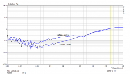
Here are some of my voltage/current comparison results - measured with a non-distorting microphone, which is essential. The tweeter benefits the least but still benefits. The 3 samples have an aluminum VC former, which according to my observations limits the current-drive distortion reduction to about 15 dB. With non-conductive formers (that is, without their eddy current distortion, that is not curable by current drive), over 30 dB drops are commonplace in third harmonic and odd-order IM products.PMA said:Now with a pure voltage drive, I get almost the same distortion and spectrum as with the current drive. So for this tweeter there is no improvement under current drive. This confirms what I measured years ago, the only notable change was for woofers.
Here are some of my voltage/current comparison results - measured with a non-distorting microphone, which is essential.
Esa,
could you explain this? (in both cases, same voltage across driver).
[microphone distortion is a non-issue in the measurements I have shown, verified by low-distortion sound source]
Attachments
Maybe depend how you hook it up...
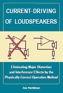
No, if FB divider has much higher resistance than the sensing resistor (almost always) and one has enough loopgain. There is no reason. Easily verifiable by distortion measurement. The image looks like to support someone's book and theory.
No, if FB divider has much higher resistance than the sensing resistor (almost always) and one has enough loopgain. There is no reason. Easily verifiable by distortion measurement. The image looks like to support someone's book and theory.
No, wait. The left is voltage control, the right is current.
jn
Have you tested any speakers with shorting rings? With a non conductive former, you should be able to see the modulation of the eddy drag as the vc is behind center position. That would require a current drive of course, as Le(x) would be a confounder.Here are some of my voltage/current comparison results - measured with a non-distorting microphone, which is essential. The tweeter benefits the least but still benefits. The 3 samples have an aluminum VC former, which according to my observations limits the current-drive distortion reduction to about 15 dB. With non-conductive formers (that is, without their eddy current distortion, that is not curable by current drive), over 30 dB drops are commonplace in third harmonic and odd-order IM products.
Have you been following the discussion of my pickup coil feedback design?
jn
ps. The page you linked to, your criticism of Klippel's analysis might be due to him using absolute levels of distortion products instead of relative. Your use of f1/f2 in the paragraph is quite confusing if it is the first thing read (which I did). Only after reading your 7 inch page and midrange page was f1/f2/fs made clear relative to each other.
Last edited:
What needs explanation is the upper portion, and sorry I still can't help suspecting the mic. 1% THD at less than 1W is highish.PMA said:Esa,
could you explain this? (in both cases, same voltage across driver)
I don't know why the contention over one set of measurements on one speaker. We all knew from the beginning that current drive works better on some speakers than others. Clearly any single speaker could be perceived to justify or dismiss the merit of current drive but it would be entirely futile.
Surely we can move past "is current drive better?" to "where is current drive useful?".
Surely we can move past "is current drive better?" to "where is current drive useful?".
and sorry I still can't help suspecting the mic. 1% THD at less than 1W is highish.
The same mic measures 0.2% with a better driver under same conditions.
Beyma T2030 is known to be quite poor, but it is the only one type I have uninstalled now. I have 3 pcs and one of them measures >3% at 2V and has sub-harmonics showing cone break-up.
Better still, a middle ground that Rod Elliott advocates and adjust the amp's output impedance to suit the speaker?
No, wait. The left is voltage control, the right is current.
jn
Right, I have overlooked speaker position. For current drive, I have a circuit with gain, with a FB divider. He shows unity (voltage) gain behind speaker, at the FB point of the sensing resistor..
Last edited:
- Status
- Not open for further replies.
- Home
- Member Areas
- The Lounge
- John Curl's Blowtorch preamplifier part III