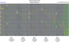
I have a 3886 amp that I'll be hooking this to but not for a few days (or maybe after Christmas the way things are going). I ordered these boxes for the test: Amazon.com: Absolute SQ6.5PKB 6.5" Square Box Speakers, Set of Two (Black) with Speaker Terminal: Cell Phones & Accessories I have a response curve I can post later. It is something of a full range driver.
Yah know, all this resistance to a scheme that could be easily implemented using a 3886 chip.
Sorry John
I have no DVC driver, let alone a DVC wound like you suggest.
But what about a circuit that would drive a 1:1 single bobbin transformer in place of the DVC driver (primary as the driven coil, secondary as the sense coil, )?
Wouldn't all the nonlinearities due to the magnetic circuit be linearized?
George
It should. It also allows you to change the magnetic non linearities as a test of functionality.Sorry John
I have no DVC driver, let alone a DVC wound like you suggest.
But what about a circuit that would drive a 1:1 single bobbin transformer in place of the DVC driver (primary as the driven coil, secondary as the sense coil, )?
Wouldn't all the nonlinearities due to the magnetic circuit be linearized?
George
If you run it with a reasonably high level, say half the VA, you could then bring a large neo magnet up against the core to saturate part of the core in one direction. Without the compensation, you should see wild things happen to the pickup voltage. With comp, the pickup voltage should be stable until the amp bites the dust, and in the meantime, you would see the distortion on the drive voltage in it's attempt to compensate the non linearities.
jn
It should
Good, thanks.
I guess I have to follow this circuit:
John Curl's Blowtorch preamplifier part III
For to make things a bit easier, can I use only one op.amp (the power amp chip) in inverting mode like I have sketched in the attached photo?
If yes, the Rs value should be 1k?
George
Attachments
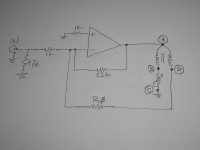
Yes. This is what I put in post #11255
If you want to see something interesting, put a pair of diodes antiparallel across your variable resistor and watch the amp attempt to linearize (except, it might kill the amp as it rails into the inductor..sorry). Better yet, put a resistor in series with the antiparallel diodes across the primary, this is to simulate a magnetic non linearity..
If you want to see something interesting, put a pair of diodes antiparallel across your variable resistor and watch the amp attempt to linearize (except, it might kill the amp as it rails into the inductor..sorry). Better yet, put a resistor in series with the antiparallel diodes across the primary, this is to simulate a magnetic non linearity..
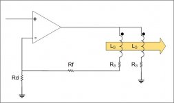
This is my idea in general. Bog simple.
Attachments
Last edited:
Thanks again.
I’ll try it in the following days.
I am sure Pavel will sim it (sanity check) 🙂
George
I’ll try it in the following days.
I am sure Pavel will sim it (sanity check) 🙂
George
Jneutron, am I correct to say that the inductance of the coil is higher when it's velocity is high because it causes the eddy current path to become longer?
As I understand the DVC circuit (as conceived initially) will behave like current drive, except the matching of the coils will be the limit on the effective series impedance. So if the coils are mismatched by 10%, the effective series impedance (if compared to current drive) will be no more than 80 ohms (or more like the EMF has been reduced to 10%). The coil leakage remains in series with the resistance and so if your leakage is 400nH, the effective 80 ohms will be 80R+4uH (Bifilar wound coils would have very low leakage).
As I understand the reason this would work better than current drive is because by changing coil position/geometry we can be selective about which EMF sources we allow to affect cone motion. However I don't think there is any useful way to extract different EMF sources using this method, and I see no application benefits over current drive. Any failure of the coils to couple perfectly results in a reintroduction of EMF which resembles lower drive impedance, but worse because differing magnetic nonlinearities between the two coils are added in.
Last edited:
Mine in blue
My comments in red..
My conclusion, as of now, is quite clear: "JN-drive" implements indirect current drive (a clear and concise name for it), just way less feasible (see below) and most likely less effective in distortion reduction (fine-print remains to be seen)(agreed). We have to mod the driver (*pita*)(see below)[special DVC, the sense coil being thin wire so as not to have lot's of "dead" copper eating volume in the gap] and the amp because we will need to install degeneration also to have some electrical damping(not sure), plus proper EQ to get a reasonable SPL curve (PMA's sim shows flat to over 1k, with a bump at 30hz, may be cabinet controlled, say a critical damped scheme.)[I meant the high Qts(=Qms in this case) bump at resonance. Qms can easily reach two-digit numbers, depending on the driver and cabinet]. Wrt damping, especially those cheaply built drivers with high nonlinearity are really prone to nasty "jump resonance" chaotic phenomena with no damping even if the acoustic loading is benign.
So, why not just impress the current directly rather than trying to isolate a quasi-constant resistor and relying on V/I transfer to obtain the current by impressing a voltage, with that V/I-transfer not being perfect since the isolated transfer resistance isn't perfect (if alone from thermal drift, and I'm sure we will find residuals of other distortions as well). And then use the dual VC(wait a cotton pickin minute, you just said above that it was a PITA, now you wanna use it?? )[standard DVC, both coils driven] to best extract the velocity signal with a balanced version of the servoing Birt bridge and degenerate the current drive with this (introducing an amount of MFB), rather than using the "polluted" terminal voltage.
As I've written before, real world check by impressing a current and looking at the distortion of the "JN-Drive" voltage will most likely reveal quite a bit of distortion left, coming from the transfer impedance imperfections, matching issues etc.(again, jury is out)
While it is not completely impossible that some of this distortion might cancel with other distortions that aren't addressed by current/JN-drive like BL(x), BL(i) and reluctance force, I would think the chances are nil.
That's what discussion and discovery is all about. I also look forward to data on harmonic distortion as well as phase out to over 3K.
What is this driver's high end response limit? looked back at Demians data and do not see anything of it's upper frequency limit.[HF response of this kind of driver is chacterized by decoupling the outer area of the cone and breakup: The harsh breakup "talks" very visibly into the impedance plot. I wouldn't use that driver above 1kHz max]
jn
Yah know, all this resistance to a scheme that could be easily implemented using a 3886 chip.
Mine in blue
We could run out of colors so easily...
Read your reply...we violently agree.
jn
Good point!As I understand the reason this would work better than current drive is because by changing coil position/geometry we can be selective about which EMF sources we allow to affect cone motion. However I don't think there is any useful way to extract different EMF sources using this method, and I see no application benefits over current drive. Any failure of the coils to couple perfectly results in a reintroduction of EMF which resembles lower drive impedance, but worse because differing magnetic nonlinearities between the two coils are added in.
responses in red.
jn
I prefer bifilar or my co-wound coils because that produces the exact same magnetic non linearities. You are correct in that if the pickup coil sees something the drive doesn't, that would not be good.Jneutron, am I correct to say that the inductance of the coil is higher when it's velocity is high because it causes the eddy current path to become longer?(no. The eddy current path is dependent on the flux rate of change within a conductive material.) The initial effect of eddy current dissipation is to increase the effective resistance of the coil. Eddy currents tend to produce a magnetic field opposing the driving stimulus, so tends to help confine the magnetic field. This effect tends to lower the inductance by confining of the stimulus field..)
As I understand the DVC circuit (as conceived initially) will behave like current drive, except the matching of the coils will be the limit on the effective series impedance. So if the coils are mismatched by 10%, the effective series impedance (if compared to current drive) will be no more than 80 ohms (or more like the EMF has been reduced to 10%). The coil leakage remains in series with the resistance and so if your leakage is 400nH, the effective 80 ohms will be 80R+4uH (Bifilar wound coils would have very low leakage).(I'm not sure how you got your numbers, it seems you are speaking of paralleling the two coils. The second non driving coil has no current in it. If the coils have differing turncount, a gain stage can compensate the feedback level to where the difference is exactly that of the drive coil Rs. I would clamp a second woofer to the first, drive it with a sine, and look for identical voltage from both unloaded coils. If the pickup has too few turns, the gain stage can be used to zero the difference.)
As I understand the reason this would work better than current drive is because by changing coil position/geometry we can be selective about which EMF sources we allow to affect cone motion. However I don't think there is any useful way to extract different EMF sources using this method, and I see no application benefits over current drive.(My method cannot choose which non linear magnetic effect to choose from, it can only see all of them) Any failure of the coils to couple perfectly results in a reintroduction of EMF which resembles lower drive impedance, but worse because differing magnetic nonlinearities between the two coils are added in.
jn
😀We could run out of colors so easily...
Read your reply...we violently agree.
jn
I would think with such a cheap DVC driver we could actually achieve a noticable improvement with an optimized amp for it, hopefully quite cost-effective. How that amp conceptually will actually look like, well that's the fun part of this, isn't it? I look forward to contribute to this when I have the drivers. I wasn't aware of this 6.5" DVC which would be ideal to complement a small current-driven cheap fullranger (3"...4") in a nice active FAST project.
I look forward to you contributions, thank you for the efforts.😀
I would think with such a cheap DVC driver we could actually achieve a noticable improvement with an optimized amp for it, hopefully quite cost-effective. How that amp will actually look like conceptually, well that's the fun part of this, isn't it?(absolutely. If we can add a lower octave and drop harmonics simply by unsoldering one feedback resistor and adding connectors to the second coil, that would be ideal (as well as my goal for a diy project for all)) I look forward to contribute to this when I have the drivers. I wasn't aware of this 6.5" DVC which would be ideal to complement a small current-driven cheap fullranger (3"...4") in a nice active FAST project.
jn
jneutron, your circuit can be solved to Re in series with 2 EMF sources opposing each other, one per coil. If one coil is 90% coupled to the other coil, the total EMF is 10% of the original EMF. So it's like 90% current drive, letting 10% of the EMF back in.
If the coils are not perfectly coupled that implies they don't occupy the same physical space, which means the leakage flux paths will encounter different nonlinearities. So you could scale the output of one coil to match the EMFs, but there will be a residual which contains only distortion. So the distortion reduction when compared to equivalent impedance drive will be less than expected. Although with bifilar winding the coupling could be very high.
Also, no rejection of thermal compression.
A 6.5" subwoofer and a 3-4" fullranger.....sorry, you've lost me 😎
Because he didn't call it WAW?
//
- Status
- Not open for further replies.
- Home
- Member Areas
- The Lounge
- John Curl's Blowtorch preamplifier part III