The difference between coils, 2nd image yellow track, almost exactly reflects inverted impedance curve of the speaker used.
It has to. It is a measure of the voltage drop on the distributed real resistance. At resonance, it will of course dip due to small currents.
and at the high end, the coil current falls off due to increasing inductance, so the voltage does as well.
jn
So if you make a compensation, you will get an equivalent to a current drive, IMO, as was simulated. You will get the same distortion as if you would have used the current drive. Am I missing something?
Yes, you are.So if you make a compensation, you will get an equivalent to a current drive, IMO, as was simulated. You will get the same distortion as if you would have used the current drive. Am I missing something?
Give me 10 minutes.
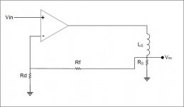
Ok...This circuit, L = 0. Vrs is Vin times (Rd+Rf)/Rd, or Vin times K, K = (Rd+Rf)/Rd.
Lets make Ls =1uH. What is the voltage at Rs? What is the phase at Rs?
2 uH..What is the voltage and phase at Rs?
The feedback is trying to keep the voltage at Rs equal to Vin times K and in phase, no matter what the inductance in series with it is (within the limit of the amp compliance voltage). AND, more importantly, no matter what that inductance is trying to do, pull or return energy to the system.
The problem historically, is how do we differentiate the actual real resistive part of the coil impedance from the terminal voltages?
We can try DSP, but we need to know the position, velocity, and acceleration of the coil in the gap.
Or, we can couple to all the inductance, and subtract it out. That is what I am doing with the co-wound pickup coil.
jn
Attachments
Last edited:
Thanks Richard, I know about and have experimented with mechanically damping speaker baskets etc.Max --- you can apply liquid 'rubber' or other damping compound (goop) to the magnet assembly and speaker frame, also. 🙂
Enjoy, clearer, cleaner sound. Better speakers will have thick/heavy cast metal magnet/frame assembly and benefit less from damping goop applied.
THx-Richard
The changes I mention are not to do with mechanical damping (the amount is not great enough nor suitably placed) but are to do with magnetic/electronic noise.....which gets transduced to acoustic noise.
Dan.
please understand that I don't bother, ie I plain don't make any of my statements until well proven, admittedly anecdotally/subjectively BUT relating matching subjective opinions of at least several subjects.
Dan you have not proved, shown, or demonstrated a single thing. The only time you tried around here you gave us two files which you said exhibited the difference you are always talking about, but nobody could hear a difference. Nobody.
I didn't spec turns per inch/foot my bad, cat5/cat6 turns ratio would be a benchmark.
I'm wanting a non directional twisted pair.....USB 90R.
I thought you believed (without evidence) that all conductors are inherently directional. So is the idea of this project to use doubled twisted pairs in each direction, so the non-existent directionality magically cancels?
Putting little dots or blobs of anything will not alter the magnetic characteristics of the bulk.Thanks Richard, I know about and have experimented with mechanically damping speaker baskets etc.
The changes I mention are not to do with mechanical damping (the amount is not great enough nor suitably placed) but are to do with magnetic/electronic noise.....which gets transduced to acoustic noise.
Dan.
But what do I know, I'm just a simple country doctor Jim. My 25 years of experience is certainly no match to your prowess in this technology.
Jn
I still can not see the part that Pavel missed.Yes, you are. ...
Come now, John, you can accuse Dan of many things, but never "subtlety" surely. He has been beating the same drum with a dull hammer for years.
Max, let's leave subtlety off this thread for now. It just annoys our critics. '-)
Be honest you don't even pay attention to what Max is talking about.
...and, BTW, John, I do not consider myself a "critic" of yours. I think once I called into question your claims about Bybee, principally because you made so many contradictory excuses (if people can't hear the difference it's because their system isn't good enough, or because it's too good). However, over all I consider myself a John Curl fan. I have been reading articles by you since the 1970s, and like Richard Marsh you are part of my audio pantheon. I have a lot of respect for your circuit innovations. I hope someday Dan does something half as interesting.
I still can not see the part that Pavel missed.
The circuit I drew is a very simple gain stage. It is designed to put the correct VOLTAGE across the resistor Rs. It does that because I am feeding back the exact reading from across that resistor to the negative feedback network.
In a single coil speaker, I do not have access to the resistive part of the coil equivalent model, I can only see the sum of the two elements Ls and Rs.
In a dual vc, I have direct access to the voltage across the L of the coil because I do not pull current through the second coil which by design the secondary of a 1:1 transformer. By subtracting that secondary voltage which is a copy of the reactive voltage across Ls, I am left with exactly the Rs part.
Because I am using only the voltage across the Rs as feedback, I am controlling the VOLTAGE across the resistor. And, my circuit does not care what the actual resistance Rs is as I am not measuring it.
This is the exact same concept as a 4 wire Kelvin connection, where you cancel out the wiring drops to the load by connecting feedback at the load. In my circuit, the circuit element you are bypassing has been bypassed creatively.
So it is NOT current control, it is voltage control. But as I said before, I am not cancelling out compression as I do not see what the value of Rs actually is.
It is possible to do that with DSP of course, as I know what the Rs voltage is, and could put a sense resistor in series with the amp output to read the current (with no impact on damping as the amp would comp it out). Knowing the voltage across Rs and the current through it as well, a DSP could calculate the real time resistance caused by heating and adjust the gain to compensate. This AGC function only has to react at the coil thermal rate of change, not at audio rates, so does not require a lot of horsepower.
Yah yah, I know, that was patentable as well...
Jn
Last edited:
Thanks Richard, I know about and have experimented with mechanically damping speaker baskets etc.
The changes I mention are not to do with mechanical damping (the amount is not great enough nor suitably placed) but are to do with magnetic/electronic noise.....which gets transduced to acoustic noise.
Dan.
I was thinking of that stick-on label attached to the back of the magnet that you mentioned ... doing some damping.
However, if it was also a metalised piece..... what affect it would have on the magnet??
-RNM
You lost me there. Voltage controlled current drive? In the mean time, please proceed anyway... So it is NOT current control, it is voltage control....
Yah yah, I know, that was patentable as well...
Jn
You're on a creative roll. 🙂 Dont stop now.
Maybe Demian will tie it into an amp and measure the before and after reduction in distortion next.
Then you can write a paper and publish it in AES
-RNM
Last edited:
You lost me there. Voltage controlled current drive? In the mean time, please proceed anyway
Huh? Voltage controlled voltage drive is what I just described.
Look, the circuitry is the easy part. What pulls blank stares is the conceptual understanding of the Ls/Rs inductor model and how I am getting the voltage across the distributed Rs out.
KSTR got this immediately.
Oh, that AGC DSP function? As a first pass, I would calculate the Rs value every millisecond, and use a 30 to 50 point running average filter to calculate the Rs at thermal rates.
Knowing copper resistance rises at .343% per degree C (IIRC), the DSP can also be used to protect the coil from thermal damage by direct monitoring of the vc temperature. Imagine a display on the amp telling you the voice coil temperature in real time..with programmable limit and kill values.
Jn
Last edited:
I am not a member of AES. I am not opposed to a collaborative effort however.You're on a creative roll. 🙂 Dont stop now.
Maybe Demian will tie it into an amp and measure the before and after reduction in distortion next.
Then you can write a paper and publish it in AES
-RNM
I do not even have a stereo setup in my house, so the chances of me listening to any improvements I discuss here is probably zero.
Jn
- Status
- Not open for further replies.
- Home
- Member Areas
- The Lounge
- John Curl's Blowtorch preamplifier part III