😀 where are you ?😀If you look at stereophile class A pre-amps, you are there but so are many other circuits. Doesn't seem you have the only magic bullet for getting a top rating from the chimp factory.
Hi Ed.Surprisingly having built the basic gain stage using Mosfets for the second stage it sounds quite good. Distortion was also low .01% ish as I recall.
It does sound different than the same gain from an LM4562.
Can you describe those (sighted subjective lol) differences.
Care to elaborate ?.My tentative conclusion is there is something going on besides THD.
I have some ideas but nothing I am able to demonstrate.
Dan.
To a point yes...tapping disc ceramics can cause audible sound in audio stage output.Would it be fair to say that a component that sing, is also an equally good microphone?
Another question is what are the effects on circuits of these electromechanical resonances that are notably right in the ears most sensitive midrange audio band.
Dan.
Mr Curl, I would like to know your opinion about Paradise phono stage, which was a subject of a large thread and group buy a few years ago. It has lower subjective noise than Pass Xono clone and Borbely J-Fet input phono preamps I also built. It has bipolar input, and as a low noise phono preamps designer you should listen to one if possible.
Attachments
Kamis, your circuit is very well implemented. It follows what I believe is important, mainly, Class A, open loop input gain stage, passive EQ, (I usually use hybrid active-passive EQ for practical reasons, but all passive EQ should be better. And while it seems very complicated initially, the signal thru-path is relatively simple. This is good, in my opinion. I can readily believe that it sounds very good in reality.
This circuit and the whole project was made by well known member of this forum Joachim Gerhard and others members of the forum team.It has zero hum and extremely low noise, I think the world record in low noise. Input bias current trough cartridge is adjustable to zero with multiturn pot.There is a 412 pages thread about this high end DIY phono stage.Kamis, your circuit is very well implemented. It follows what I believe is important, mainly, Class A, open loop input gain stage, passive EQ, (I usually use hybrid active-passive EQ for practical reasons, but all passive EQ should be better. And while it seems very complicated initially, the signal thru-path is relatively simple. This is good, in my opinion. I can readily believe that it sounds very good in reality.
There is a 412 pages thread about this high end DIY phono stage.
Joachim, Hesener and Frans de Wit I think
Paradise Builders
Taking into considering also Paradise’s predecessor (MPP), a real give-away collaboration

George
This is a good design, but it is made with compromises in mind. Most designs are made this way. In this case, jfets are used at a minimum, and inexpensive bipolars are used instead. Pch jfets are not used at all, because at the time this design was made, Pch jfets were becoming more and more expensive and hard to find. This is a very quiet design, but not the quietest possible as shown by the 33ohm resistors in each emitter. This limits the noise floor, because other noise inputs must add as well into the input noise, but it is more than quiet enough.
I started out this way with the early Levinson JC-1 pre-preamp in 1973, with 8 paralleled complementary devices, each with a 10 ohm resistor in series. If I used the later found input devices like the PE8050-PE8550 that I used in 1979-81, with this early JC-1 circuit, I would have built an even quieter input stage than this DIY phono stage, just because the 10 ohm resistors used are a smaller value than the 33 ohm resistors used in the Paradise design.
I started out this way with the early Levinson JC-1 pre-preamp in 1973, with 8 paralleled complementary devices, each with a 10 ohm resistor in series. If I used the later found input devices like the PE8050-PE8550 that I used in 1979-81, with this early JC-1 circuit, I would have built an even quieter input stage than this DIY phono stage, just because the 10 ohm resistors used are a smaller value than the 33 ohm resistors used in the Paradise design.
I think the world record in low noise.
No this would be the Lepaisant amplifier .06nV/rt-Hz.
^ https://pdfs.semanticscholar.org/49b5/63335faea2836e65c6dee411d5c8b04d5a3e.pdf
That's a trip of a feedback arrangement for sure.
That's a trip of a feedback arrangement for sure.
No this would be the Lepaisant amplifier .06nV/rt-Hz.
There is a close 2nd: 70 pV/rtHz test ampliifer in AOE V3 [1], chapter 8.5
No transformers, Zetex-based.
You should have that book, especially if you have slept for 45 years. 😀
G.
[1] Paul Horowitz, Winfield Hill, The Art Of Electronics, 3rd edition
< The Art of Electronics: Amazon.de: Paul Horowitz, Winfield Hill: Fremdsprachige Bucher >

OMG. This self-adulation thread takes the next round.
But we won't fall victim to a proof by reductio ad nauseam.
But we won't fall victim to a proof by reductio ad nauseam.
There is a close 2nd: 70 pV/rtHz test ampliifer in AOE V3 [1], chapter 8.5
No transformers, Zetex-based.
You should have that book, especially if you have slept for 45 years. 😀
I have acquired some of the NPN Zetex devices. When brave I will get some PNPs as well. I currently have no need for such low noise levels, but nice to have the option 🙂
We have only gotten started with my personal approach to designing audio electronics, but the road seems to continually be diverted. I would hope to go a little further, but I think I have run out of energy.
Perhaps another linear audio topic can be suggested?
Perhaps another linear audio topic can be suggested?
John I would be interested to hear how, and in what ways, the later versions are superior to the earlier ones. I have seen those pictures here before but you don't say much about why they are superior, how they compare to each other, etc.
^ https://pdfs.semanticscholar.org/49b5/63335faea2836e65c6dee411d5c8b04d5a3e.pdf
That's a trip of a feedback arrangement for sure.
Interesting use of the AD844 as IC2. I wonder why that specific chip, which really is a current conveyor rather than an opamp per se? Scott?
Jan
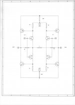
I want to go forward now with my original intent. When the 4Q jfet input stage is finally known and understood, then other variations can be useful. Here are two diagrams showing fully balanced operation.
John,
What s the benefit of including the source resistors R11~14 ?
Would they not reduce the effective transconductance of the JFETs ?
Does the improved linearity overrides the gm loss ?
Patrick
Interesting use of the AD844 as IC2. I wonder why that specific chip
The upstream IC (LT1028) has min GBW=50MHz and is operated at a gain of 39, so its bandwidth is about 1.3 MHz. The AD844 is operated at a gain of 14 and at that gain, has BW of about 33 MHz (ADI datasheet Fig 24). It seems to me the AD844 was used because its bandwidth is 25X higher than the first stage, thus it "stays out of the way" and allows the other, slower, circuits to determine full loop bandwidth. Which appears to be, extrapolating Figure 4, about -3dB @ 400 kHz (-1dB @ 100 kHz).
- Status
- Not open for further replies.
- Home
- Member Areas
- The Lounge
- John Curl's Blowtorch preamplifier part II