Now that the 'peanut gallery' has made their criticisms, I will go forward with MY VERSION of high quality audio electronic design.
Frankly your posse doesn't quite understand FET's, which is understandable because none of you have any understanding of the underlying semiconductor physics. If I went on I would probably offend many here, better to just let it pass, ignorance is bliss.
You are right, Scott, I do not have a good working knowledge of semiconductor physics. It is not what makes the difference when it comes to circuit design. Circuit design is optimizing REAL devices that are usually made by other manufacturers in a circuit that performs as nearly ideal as possible. Real devices have characteristics that can be measured or taken from data sheets of the devices as measured and graphed by others. That is all we need.
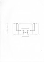
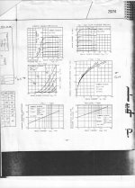
Now here is an excellent example of a jfet data sheet which will give us a great deal of information as to how this device will mate with a 'complement' jfet and other useful characteristics. Also, here is an example of the same JC-2 sort of circuit made with all fets. Either jfets or mosfets can be used for the second stage.
Attachments
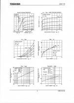
It seems to me, that circuit needs PJFETs and NJFETs that are gm matched , rather than IDSS matched. IDSS matching simply means that the midpoint of the shared source "tail" resistor, is exactly zero volts. But if the gm's are not matched, you'll get distortion in the second stage because the push- (PJFET) and the pull- (NJFET) currents (the signal currents) are not equal.
Maybe people actually do want the push- and the pull- signal currents to be equal, so they actually do want gm matching ... BUT it's so much easier in the lab to measure IDSS than to measure gm! Maybe people take the easy way out: measure and match IDSS. And then they hope that IDSS-matched devices will also turn out, by the grace of God, to have pretty close gm too.
Maybe people actually do want the push- and the pull- signal currents to be equal, so they actually do want gm matching ... BUT it's so much easier in the lab to measure IDSS than to measure gm! Maybe people take the easy way out: measure and match IDSS. And then they hope that IDSS-matched devices will also turn out, by the grace of God, to have pretty close gm too.
, I will go forward with MY VERSION of high quality audio electronic design.
High quality audio or high quality marketing copy? I get confused. Sounds very much like Bruno's road to audio hell 'specify the design and accept the performance'?
It seems to me, that circuit needs PJFETs and NJFETs that are gm matched , rather than IDSS matched. IDSS matching simply means that the midpoint of the shared source "tail" resistor, is exactly zero volts. But if the gm's are not matched, you'll get distortion in the second stage because the push- (PJFET) and the pull- (NJFET) currents (the signal currents) are not equal.
Looks pretty much exactly what Pavel's sims show (in his very simple model)
Distortion in JFET input stage circuits
PS, why not try something like Samuel Groner's fully-complementary transimpedance stage on even larger rails with the appropriate bootstrapped cascoding of the diff pair and even more (wasteful) resistance in the current mirror (as to push the noise down further). Then go crazy with gm/c and noise in the input pair.
Surprisingly having built the basic gain stage using Mosfets for the second stage it sounds quite good. Distortion was also low .01% ish as I recall.
It does sound different than the same gain from an LM4562.
My tentative conclusion is there is something going on besides THD.
I have some ideas but nothing I am able to demonstrate.
But it is a simple circuit to build and try for yourself.
Quite simply once THD drops below perceptual levels, who cares?
(Now what level is perceptual is a different issue!)
PS, why not try something like Samuel Groner's fully-complementary transimpedance stage on even larger rails with the appropriate bootstrapped cascoding of the diff pair and even more (wasteful) resistance in the current mirror (as to push the noise down further). Then go crazy with gm/c and noise in the input pair.
Derfy,
Did you just go from complementary doesn't matter to it does?
Mark Johnson makes a good point, although not a super important one, because many 'useful' complementary jfets for this application have similar Gm at the same approximate current. For example, compare the 2SK170 with its complement, the 2SJ74. Look at 2 ma for example or another current. The Gm's track pretty well. Even if the Gm's are slightly off, this can be compensated for with some local feedback on one pair, or you can just ignore it and put up with a small increase of distortion.
Now, here is the difference between what I am trying to show and what many here are attempting me to believe in:
What is important is designing the most linear, shortest thru-path for the audio signal. Less stage count, and highest open loop linearity, along with high open loop bandwidth are my key parameters for successful audio quality. Not lowest thd, due to lots of feedback or complicated buffers, etc. My criteria is about 0.01% distortion or less at operating level, even a little more at output peaks, BUT it has to be almost entirely 3rd harmonic, with some 2'd being tolerated.
I come from the world of analog tape recording, where 0.1% is an amazingly low level of pure 3'rd and is only found at low levels, and 1-10% is more typical on peaks, yet the sound can still be OK, subjectively. However, harmonics above 4th harmonic must be virtually suppressed, if the sound quality is to be maintained. This means that xover distortion, or even bipolar transistor non-linearity may destroy the sound quality, even though the added higher order thd from these other sources may be almost unmeasurable.
Attachments

That would be a step backwards. It was already done, even before complementary fets were generally available. The 4Q jfet input stage is primary to make the circuit successful, for the most part. The second stages, etc can be bipolar if necessary, but a bipolar input will always be a compromise. The next best is a jfet differential input with a folded cascode load to keep a balanced to single ended design linear. ADI have made this with the AD825 and Dimitri makes a wonderful all discrete 'equivalent' for Mark Levinson products today.
Then we have the trade-off between the bipolar differential circuit with a folded cascode load, like the AD797, or a full complementary differential bipolar input stage like we originally designed with , years before the complementary jfets became available.
Then we have the trade-off between the bipolar differential circuit with a folded cascode load, like the AD797, or a full complementary differential bipolar input stage like we originally designed with , years before the complementary jfets became available.
Derfy,
Did you just go from complementary doesn't matter to it does?
No, not really, I'm just throwing out that, *if* you want complementary in a world where p-jfets aren't really that available, why not look elsewhere? I'm generally circuit agnostic -- if it works, it works.
Why not do something a bit more 21st century rather than re-hashing old circuits...
Class D?
There is plenty of room for others, especially on other threads. However, my circuits are still on top as far as audio reviewers are concerned.
I understand that the cost of the input jfets can be costly, but it appears to still be possible to purchase them from even this website. What is the problem?
I understand that the cost of the input jfets can be costly, but it appears to still be possible to purchase them from even this website. What is the problem?
What is the problem?
Not complaining here. Please proceed.
No, not really, I'm just throwing out that, *if* you want complementary in a world where p-jfets aren't really that available, why not look elsewhere? I'm generally circuit agnostic -- if it works, it works.
As the comedian said to the heckler "I work alone."
Replied the heckler "Then you're a man short."
. However, my circuits are still on top as far as audio reviewers are concerned.
If you look at stereophile class A pre-amps, you are there but so are many other circuits. Doesn't seem you have the only magic bullet for getting a top rating from the chimp factory.
Would it be fair to say that a component that sing, is also an equally good microphone?
Examples of Noise Countermeasures (Video) | Ceramic Capacitor | Murata Manufacturing Co., Ltd.
//
Examples of Noise Countermeasures (Video) | Ceramic Capacitor | Murata Manufacturing Co., Ltd.
//
- Status
- Not open for further replies.
- Home
- Member Areas
- The Lounge
- John Curl's Blowtorch preamplifier part II