Chris I figure it is at least two chips and maybe more for a product no longer supported by the folks who now own the name! Let someone else use it as is or fix it.
We probably have 20 or more pieces to eBay every year.
We took a high quality projector that was two years old in and gave it to an inner city church. They returned it as it did not do HDMI in. So it went to eBay.
Later they realized the projector they got couldn't handle their computer's screen resolution and they didn't have the chops to lower it. A common problem. Computers keep improving and projectors have to follow.
So quite simply I don't have enough places to give away gear!
So what's a Revox A77 1/4 track machine with 3 3/4 and 7 1/2 ips worth today? Probably need at least a few new caps as the things been sitting for over 25 years! It does run though.
$100 to $400 depends on version I to IV. And of course condition.
$500+ if parted out over time.
$500+ if parted out over time.
Hi Ed,
There's no faulting you for that. They don't want the product fixed for starters, and constricting parts and service information serves that end.
Me? I'm still trying to raise my own test equipment to the level needed to do the work I am trying to do. I collect HP gear as well as use it.
At the end of the day, if you can't find equipment a good home it goes to Ebay. Something I'm not prepared to do.
-Chris
There's no faulting you for that. They don't want the product fixed for starters, and constricting parts and service information serves that end.
Yes, I'm finding that out as well. Mind you, there maybe people here that are close to you that would go for your excess. Not having to ship it must be attractive to you.So quite simply I don't have enough places to give away gear!
Me? I'm still trying to raise my own test equipment to the level needed to do the work I am trying to do. I collect HP gear as well as use it.
At the end of the day, if you can't find equipment a good home it goes to Ebay. Something I'm not prepared to do.
-Chris
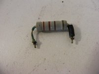
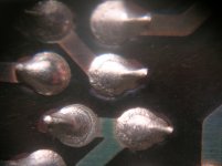
Never saw this before. A resistor used in a power supply feeding a zener diode. Spaghetti on the leads to make sure it couldn't short to its' neighbors. Four of them. 330 ohm 3 watts. After they baked in I could not unsolder them! One had dissolved the solder joint and only started to conduct after things warmed up a bit. Good thing this is all that was wrong, the replacement card from the manufacturer is $1,100.00. Yes I did have to add jumpers to replace the destroyed PC traces.
Yes a bit of browning on the card, but the unit has been in service since 2001.
Yes a bit of browning on the card, but the unit has been in service since 2001.
Attachments
Hi Ed,
That's pretty common with some manufacturers. Some look like that after a couple (as in two) years! In some cases they may be trying to get into the lower zener dynamic resistance and cook everything needlessly. What does the zener diode look like?
Sometimes that circuit can be redesigned to use a reasonable current source and a darlington pass transistor arrangement. Not horribly complicated, but if you can save a few watts of dissipation, why wouldn't you?
-Chris
Chris I just used a higher wattage part. Every other part is still fine. I figure if they last another 16 years that the system will be retired before then.
The change to the solder and the leads disintegrating even though the resistor stayed on value are what I found really concerning.
The change to the solder and the leads disintegrating even though the resistor stayed on value are what I found really concerning.
Last edited:
http://www.diyaudio.com/forums/the-...owtorch-preamplifier-ii-1922.html#post5183792
"I might be tempted to build the FET version later, just for fun."
Done in less than a day including taming oscillations.
I do not have LT1792 (as used in the Spice because the model is accurate), so used OPA604.
It has somewhat higher idle current (5.2mA), so the FET bias resistors have to be changed to 1.1k.
And even with bandwidth limiting to 100kHz in the feedback network, it still needs a Zobel to be stable.
Pretty aggressive at 1.8R-1µ.
Else pretty much as simulated.
Patrick
.
Attachments

The change to the solder and the leads disintegrating even though the resistor stayed on value are what I found really concerning.
It's not uncommon. It's low cycle fatigue on the solder. It was very common back in the telco days.
The issue was up on the poles and the temp swing day to night.
Solder shrinks about 15% when it solidifies, so large fillets are essentially born with tensile stress. Repeated warm/cold cycles caused creep of the solder.
This was a typical failure mode on pc boards used on furnace control cards, the large relay socket pins soldered to the board would crack the solder right where it attaches to the pin.
If one is lucky, it is found and fixed before the traces burn up, otherwise you have to solder bare copper wire on the traces to repair.
Edit: as I recall, IBM or Bell labs actually make a soldering wave line using bismuth to zero out the phase change volume loss. Also, iirc, I mentioned this previously in this thread, maybe 5 years ago..
Jn
Last edited:


Edit: as I recall, IBM or Bell labs actually make a soldering wave line using bismuth to zero out the phase change volume loss. Also, iirc, I mentioned this previously in this thread, maybe 5 years ago..
Jn
https://www.smtnet.com/library/files/upload/advantages_of_bismuth_based_alloys_for_low_temp_soldering.pdf
Study on creep fatigue behaviour of soft solders die attach for power package applications (PDF Download Available)
http://mate.tue.nl/mate/pdfs/1504.pdf
George
I would have loved to grab all those Studer parts! Couldn't afford all that likely. They probably dumped the Revox parts decades ago. 🙁
Hey Richard,
I have a Tascam BR-20, 15 ips half track machine with no belts, all direct drive. I just hope that those parts haven't been dumped!
Mainly need to replace the idler and/or pinch roller for smooth operation.
Then finding the brake pads. They wear out faster with 15 ips and heavier 10.5 inch reels.
-RM
Hi Richard,
That's for sure. I did Revox and Tascam warranty,along with others. I had a steady diet of open reel machines and I used to help out at "The Metalworks" recording studio as well. We also received a ton of open reel machines from musicians on up to small recording studios. That was work I enjoyed doing. Good cassette decks were also enjoyable to work on. Too bad I left all my jigs and test tapes with the shop when I sold it. Most of my work was with 10 1/2" machines, and the BR-20 is only 10 1/2". Those little Revox decks like you have were also nice to work on in their way. Much nicer than stuff by Sony or even Technics. The DAT machines were okay to work on as well. We did a lot of DA-88 machines for "Colour by DeLuxe" and others. We saw them about every 1,000 hours with head changes around the 2,000 hour mark (longer if we installed the head originally).
You've got to check the capstan bearing! Those go slowly and eventually run the tape in towards the mechanism. If the tape is getting ragged on the inside, the bearing has been toast for a while. Look for tape that "wants" to stay on the inside edge of the tape guides just before the capstan shaft. That's probably the earliest warning unless you check on the heads with a grease pencil every so often.
-Chris
Hi Ed,
Those later pictures of solder failure, or "reflow" are pretty typical in consumer equipment. One would hope that the pro-audio gear was designed a bit better, but some was at least as bad as consumer stuff.
Once the solder had reflowed badly, the component lead would be so oxidised that you had to remove and resurface it or even replace the part if you ever expected the new solder to wet. For sure you were removing the old solder best you could and applying new, sometimes with extra flux.
-Chris
Yes, so did we. At times mounting the resistor on the other side of the board, or drilling holes for air flow under it/them was needed.Chris I just used a higher wattage part.
Those later pictures of solder failure, or "reflow" are pretty typical in consumer equipment. One would hope that the pro-audio gear was designed a bit better, but some was at least as bad as consumer stuff.
Once the solder had reflowed badly, the component lead would be so oxidised that you had to remove and resurface it or even replace the part if you ever expected the new solder to wet. For sure you were removing the old solder best you could and applying new, sometimes with extra flux.
-Chris
BACCH4Mac Audiophile Edition 3D Audio Playback System | AudioStream
The BACCH now available in mac mini form for a snip at $5k (6k if you want the magic with headphones). Apparantly awesome 3D soundfield for a single listener, with great gobs of DSP and head tracking. So in one way a real step forwards, in another a huge step back as it reinforces the sad single audiophile stereotype.
The BACCH now available in mac mini form for a snip at $5k (6k if you want the magic with headphones). Apparantly awesome 3D soundfield for a single listener, with great gobs of DSP and head tracking. So in one way a real step forwards, in another a huge step back as it reinforces the sad single audiophile stereotype.
There are a couple of mechanisms on solder that leads to failure. Jneutron is right, there is fatigue from thermal expansion mainly from the board. PCB's are laminates with an-isotropic thermal expansion with the highest value being thru its thickness, which is were a lot of failures are. The fatigue life of solder being deflected at the maximum, within hooke's law or its spring constant is about 10^3 cycles.Once solidified, the solder and PCB/component continue to cool pre-stressing the solder at up to it's yield because if its malleability.
Next is the temperature cycle during bonding. the most forgiving is SnPb. But the lead free most being eutectics have to be controlled carefully as there is alloying and desired result requires a phase change The wrong phase, the failure thru whiskers etc. Also, without a forming gas, oxidation can be present.
Next is the temperature cycle during bonding. the most forgiving is SnPb. But the lead free most being eutectics have to be controlled carefully as there is alloying and desired result requires a phase change The wrong phase, the failure thru whiskers etc. Also, without a forming gas, oxidation can be present.
Last edited:
- Status
- Not open for further replies.
- Home
- Member Areas
- The Lounge
- John Curl's Blowtorch preamplifier part II