SID: Slew Induced Distortion (I assume your not asking about an old relative).
Slew rate can mean two things. Max rate of change where the internal circuitry is mostly saturated or max rate of change where feedback still has some control. Outside of audio slew rate was figured as 3% distortion at full output converted to V/uS. In practice its really hard to see legitimate audio getting near either limit. Mistracking, EMI, RFI, DAC outputs etc. are another story.
Slew rate can mean two things. Max rate of change where the internal circuitry is mostly saturated or max rate of change where feedback still has some control. Outside of audio slew rate was figured as 3% distortion at full output converted to V/uS. In practice its really hard to see legitimate audio getting near either limit. Mistracking, EMI, RFI, DAC outputs etc. are another story.
While not trivial measuring differential phase to a very high resolution can be done to verify John's note. I can see how an active load would have its capacitance change with voltage (typical of most semi junctions) and that can modulate phase. If you are low or out of loop gain its harder to mitigate. This would be important in an oscilloscope or video amp where gain is not unlimited. Measuring differential phase at 1 KHz would be more involved but not that difficult.
Cordell built analog quadrature phase resolving IMD hardware to test his MOSFET Error Correction PA in early 80's
http://citeseerx.ist.psu.edu/viewdoc/download?doi=10.1.1.568.9322&rep=rep1&type=pdf
today with sub ns jitter, >110 dB S/N audio ADC in cheap soundcards its not that hard to resolve - with great sensitivity by looking for the 90 degree differential displacement of upper vs lower sidebands of "PIM" IMD products vs "AM" IMD products
so you are really thanking John for being wrong all these years and continuing to mislead on the issue in the face of overwhelming technical analysis, peer reviewed publications AND measured hardware
Don't know the whole history of what JC has said, but recently he claimed that he subjectively preferred the sound of a particular amplifier topology, or at least that's was my impression. He did not say it measured better. Hard to be wrong if a claim is formulated as a personal, subjective one. Might you be conflating some past things he said with what he recently said here? If so, perhaps he has changed his views somewhat?
Last edited:
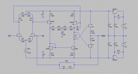
Sorry folks for the look of the schematic. It was first drawn up almost 40 years ago by my Swiss Technician, and the clean copies were destroyed in a firestorm about 25 years ago.
I took the liberty to redraw in LT Spice.
Hope I did not make any mistakes. Please let me know if you spot any,
Not certain about a few components :
J1, J3 J113 ?
Q1, Q2 2N4403 ?
Q3, Q4 2N4401 ?
C1, C9 100n ?
R15 ?
R16 ?
C10 ?
Patrick
.
Attachments
read again?
this is a strictly technical claim, has a EE theory and measurement decidable truth value
there are some conditions, under some assumptions R may not be worse, but shouldn't be better on resulting differential phase in a feedback amp's output - particularly if the designer's are even up to Cordell, Self book level of audio amplifier design
and didn't the local discussion touch on cascodes?
as long as John sticks strictly to "amps designed to Otala's prescription of flat open loop gain over audio frequencies sounds better to me and my buddies whos ears I trust" I agree there is no direct refutation
of course the Psychoacoustics of human resolution of phase modulation peters out below ~1% levels and reasonable amps put these products another few orders of magnitude down
Active loads usually cause increased differential phase, and a good reason for using resistors instead.
this is a strictly technical claim, has a EE theory and measurement decidable truth value
there are some conditions, under some assumptions R may not be worse, but shouldn't be better on resulting differential phase in a feedback amp's output - particularly if the designer's are even up to Cordell, Self book level of audio amplifier design
and didn't the local discussion touch on cascodes?
as long as John sticks strictly to "amps designed to Otala's prescription of flat open loop gain over audio frequencies sounds better to me and my buddies whos ears I trust" I agree there is no direct refutation
of course the Psychoacoustics of human resolution of phase modulation peters out below ~1% levels and reasonable amps put these products another few orders of magnitude down
Last edited:
When people write, they don't always anticipate every possible objection. Often there is some conversation back and forth if further clarification is needed. It doesn't necessarily always occur to people speaking in casual conversation to preface a statement with a disclaimer to the effect that something is believed to be a reasonable hypothesis, but has not been rigorously investigated. Certainly, I don't recall anyone in this forum whose posts I have read speaking so cautiously. At a scientific meeting among professionals, things might be different.
EDIT: Agreed JC would probably be wise to tread carefully with his claims here, knowing that if he misspeaks it will attract criticism. Not everybody here is held to that high standard obviously, but as a practical matter he apparently is, and evidently as a result of some past claims and disputes. I would suggest to him this might a good point at which to leave some of that old baggage behind.
EDIT: Agreed JC would probably be wise to tread carefully with his claims here, knowing that if he misspeaks it will attract criticism. Not everybody here is held to that high standard obviously, but as a practical matter he apparently is, and evidently as a result of some past claims and disputes. I would suggest to him this might a good point at which to leave some of that old baggage behind.
Last edited:
I took the liberty to redraw in LT Spice.
Hope I did not make any mistakes. Please let me know if you spot any,
Not certain about a few components :
J1, J3 J113 ?
Q1, Q2 2N4403 ?
Q3, Q4 2N4401 ?
C1, C9 100n ?
R15 ?
R16 ?
C10 ?
Patrick
.
Does the circuit work for you, Patrick, in LT Spice?
the purported the causal link of PIM to "low open loop gain corner frequency" is the problem with giving John a pass on this
ccs VAS load typically give just that and can give superior PIM performance at the amp output - with a little attention to the real relations governing open loop gain/phase result in the output under negative feedback
and our reminding him yearly on this forum when he comes back to the flawed implication for over a decade now suggests it really isn't informal/lazy communication but rather his underlying belief
Cordell built analog quadrature phase resolving IMD hardware to test his MOSFET Error Correction PA in early 80's
http://citeseerx.ist.psu.edu/viewdoc/download?doi=10.1.1.568.9322&rep=rep1&type=pdf
today with sub ns jitter, >110 dB S/N audio ADC in cheap soundcards its not that hard to resolve - with great sensitivity by looking for the 90 degree differential displacement of upper vs lower sidebands of "PIM" IMD products vs "AM" IMD products
I was talking about differential phase, i.e. phase change vs. voltage. its an issue in video amps where white vs. black levels can change the phase relationships of details and color subcarrier. Its better described here: https://en.wikipedia.org/wiki/Differential_phase Its probably related to PIM but not the same. I would just use either a phase meter or a network analyzer. Both straightforward if not cheap.
Going forward when discussing certain matters, perhaps he might be willing to say something like," In my personal view, and while others may see it differently, ..." When discussing issues known to be under open dispute. Might save everyone some unneeded aggravation.
I kind of suspect he is looking for technical reasons to explain why he finds the sound of one circuit preferable to another. Something brains are strongly inclined to do. When that happens, it isn't usually out of evil intent. The most import thing here is that readers not be led to some harmful misunderstanding. A reasonable disclaimer at the beginning of a post may help prevent any such ill effect, at least when a contentious subject is being discussed.
I kind of suspect he is looking for technical reasons to explain why he finds the sound of one circuit preferable to another. Something brains are strongly inclined to do. When that happens, it isn't usually out of evil intent. The most import thing here is that readers not be led to some harmful misunderstanding. A reasonable disclaimer at the beginning of a post may help prevent any such ill effect, at least when a contentious subject is being discussed.
Last edited:
I took the liberty to redraw in LT Spice.
Hope I did not make any mistakes. Please let me know if you spot any,
Patrick
.
You got the AC balance (P2, R5,R6) on the collectors where it should be on the emitters of the differential pair. That would have a pretty dramatic effect on the overall gain.
You got the AC balance (P2, R5,R6) on the collectors where it should be on the emitters of the differential pair. That would have a pretty dramatic effect on the overall gain.
Correct. It must be moved to emitters.
Attachments
JCX, I was just talking to Walt Jung today by phone. We have few if any intellectual differences between us about op amps. Who do you think first recommended the AD825 to me, Scott? NO! It was Walt. He recommended it to me because it has a 20KHz open loop bandwidth, and it sounds good. Scott just supplied me with samples of the AD825. Who turned me on to Barrie Gilbert's article on PIM? Walt, once again. And so it goes!
PIM is going to be more and more important when we finally get better, and easier to use test equipment to measure it. It might not be the only answer to audio electronics fidelity, but it is certainly worth minimizing. As time goes on, we will probably find other things, but I will stick with what sounds good, and appears to be circuits with high open loop bandwidth, good slew rate, and open loop 'stable', as well as low distortion. For the record, the circuit that I put up is 40 years old! It can be bettered, but only if the fundamental properties of the design are kept. High feedback is not the right direction to go, in my experience.
PIM is going to be more and more important when we finally get better, and easier to use test equipment to measure it. It might not be the only answer to audio electronics fidelity, but it is certainly worth minimizing. As time goes on, we will probably find other things, but I will stick with what sounds good, and appears to be circuits with high open loop bandwidth, good slew rate, and open loop 'stable', as well as low distortion. For the record, the circuit that I put up is 40 years old! It can be bettered, but only if the fundamental properties of the design are kept. High feedback is not the right direction to go, in my experience.
Last edited:
Stupid mistake of mine.
PMA,
Could you kindly post your asc file ?
I cannot read some of your values.
I believe the original FETs in John's schematics has a much higher Idss, more like >20mA.
Hence the need to use negative gate bias.
Patrick
PMA,
Could you kindly post your asc file ?
I cannot read some of your values.
I believe the original FETs in John's schematics has a much higher Idss, more like >20mA.
Hence the need to use negative gate bias.
Patrick
Many thanks.
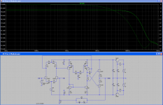
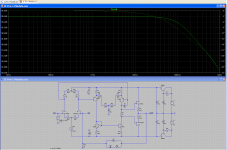
Here slightly modified, self-contained Spice files for FFT and for Frequency response.
I changed P3 to 500R so that bias is at ~8mA with no degradation on THD.
And R16 to 100R to reduce the small local peak at ~ 15MHz.
Using Toshiba JFETs (2SK170/2SJ74).
As you said, not optimised.
And probably would be equally good with only 2SK209s (with all NJFET at the output instead of complementary)
Hope John would not mind us messing with his brain child.
Patrick
.
Attachments
Last edited:
Who turned me on to Barrie Gilbert's article on PIM? Walt, once again. And so it goes!
Using a model with 741 type BW. A little positive feedback to the offset null and you can make the AD825 have 20Hz open-loop BW it will make no difference. Jcx should probably give up, this will never lead anywhere. These op-amps have poor open-loop gain due to loading/lack of cascodes on the Vas or low input transconductance or only one gain stage nothing more.
EDIT - The AD825 also has the cap load drive crossover distortion enhancer. There is a pattern developing here, this could be worth looking into.
Last edited:
AD825 "sounds good", but has limitations:
- very low OLG so it is good only for low gain like 1 - 10
- quite high noise which makes it suitable only for gain 1x, as a link stage
- not very low distortion
So the only advantage is the JFET input stage. I was playing with this opamp in 2002 and then abandoned it.
If John likes it so much, then I would like to turn his attention into ADA4898
ADA4898-2 Datasheet and Product Info | Analog Devices
- Status
- Not open for further replies.
- Home
- Member Areas
- The Lounge
- John Curl's Blowtorch preamplifier part II