Look familiar 🙂
Never knew about Ambery. Just found their website. Looks like your specimen may have become rare. Maybe worth more than you paid someday.
I still have some Event Tria self-powered speakers around here somewhere. Um, don't use them much, but don't want to toss them either.
Last edited:
Never knew about Ambery. Just found their website. Looks like your specimen may have become rare. Maybe worth more than you paid someday.
I still have some Event Tria self-powered speakers around here somewhere. Um, don't use them much, but don't want to toss them either.
Same footprint as Bill's, same two boards inside but different chipset (Crystal) and still 4558. Ambrey makes all kinds of stuff, the box that rips the audio out of the HDMI stream might be useful. I figure all these companies are one in the same or share the innards of these devices..
Last edited:
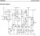
Can't you guys recognize an OP AMP when you see one? '-)
Of course, I substituted my own discrete OP AMP for any IC based one that could be stuck in the same place, except when it came to servos. 709? Is that some sort of insult? I was working and testing 709's, 50 years ago, and I know their limitations. That big triangle in my schematic is MY OP AMP, just like I told you at first. A 5534 would just not be as good in that application, at the time, although it would measure OK.
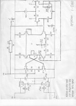
Sorry folks for the look of the schematic. It was first drawn up almost 40 years ago by my Swiss Technician, and the clean copies were destroyed in a firestorm about 25 years ago. I got this copy from old records, so old that they did not get burned since they were in an old file cabinet at my lab. I made better, fully balanced op amps later for Dave Wilson's record board in the late 80's.
Of course, I substituted my own discrete OP AMP for any IC based one that could be stuck in the same place, except when it came to servos. 709? Is that some sort of insult? I was working and testing 709's, 50 years ago, and I know their limitations. That big triangle in my schematic is MY OP AMP, just like I told you at first. A 5534 would just not be as good in that application, at the time, although it would measure OK.
Sorry folks for the look of the schematic. It was first drawn up almost 40 years ago by my Swiss Technician, and the clean copies were destroyed in a firestorm about 25 years ago. I got this copy from old records, so old that they did not get burned since they were in an old file cabinet at my lab. I made better, fully balanced op amps later for Dave Wilson's record board in the late 80's.
Now Damian asked me what is so special about this OP AMP? Well nothing, really, for a good DISCRETE design. It is almost balanced push-pull in operation, it uses jfets both on the input and output (the output fets have to be matched for idss), the input jfets were one of the first plastic packaged dual jfets available in the late 70's. The 4 bipolar transistors in the middle were in a common package and beta matched at the factory for 10% or so match to each other and high beta. One real change was the addition on the replaceable circuit board of the bipolar cap multipliers that gave superior power supply and other stage rejection, not just depending on the OP AMP for this. As can be noted, we could change various values and types of passive parts, depending on what we had at the moment. Years later, I would remove the tantalum caps, mica bypasses, and improve the current source at the input stage, as I learned more and more.
That all sounds like conventional engineering, no magic. Makes perfect sense. The Jfet output is unusual, it would have a higher output impedance than bipolar. Was that an issue ever?
This sort of reminds me of what people like say Burson are offering now, op amps made of discrete devices. I've one heard one, and for a short while, but that short experience left me underwhelmed. It seems, once again, that it's not so much what you use as how well you use it.
Same footprint as Bill's, same two boards inside but different chipset (Crystal) and still 4558. Ambrey makes all kinds of stuff, the box that rips the audio out of the HDMI stream might be useful. I figure all these companies are one in the same or share the innards of these devices..
They certainly look the same. I wonder how many are out in the wild. I like the switchable inputs. Dare say I could glom one of the ESS9023 boards in there one day, but again, rule one, never take out your one working example just in case. 🙂
OK, what makes an exceptional audio circuit? In my experience, making circuits as OPEN LOOP linear as possible is a first step. This means Class A operation from input to output, balanced push-pull operation where practical, and even using j-fets instead of bipolar devices to reduce the higher order distortion of the gain cell. In my opinion, it is not the total distortion that is very important, but the amount of higher order distortion, both AM and FM that might be generated, especially with an added feedback loop.
Higher open loop bandwidth is also important, and this limits the DC gain of the op amp, and usually disqualifies active loads on the input stage. Of course, gain-bandwidth has to be as high as practical, in order to increase the open loop bandwidth to its maximum, and still have some extra gain to use as feedback.
If you look carefully, you will find that compared to the 5534, for example, (the contender at the time to replace this discrete circuit board), you will find what I would call, one and 1/2 LESS stages in the discrete op amp. The output doesn't need a Darlington or its equivalent to be linear enough, which eliminates 1/2 stage (by my count) and the single ended driver is also omitted, and what do you know, the overall discrete circuit has a higher slew-rate than the 5534 and probably most of the competing op amps today, 40 years later.
The built in cap multipliers isolate each gain block from any others, both L and R and from any power supply transients. I add this or its fet equivalent to virtually all of my designs, even those that are IC based.
This design needs updating to be practical today, perhaps an all fet version.
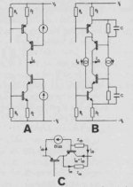
Here are two schematics to compare to:
JC, what's cut off at the top of your schematic? It kind of looks like input protection diodes for one thing?
Hi John,
Most of the active load circuits are there to allow the active device to work more linearly than it would with just a resistor. The distortion and sound quality seem to improve when there are these more advanced circuit techniques. I'm talking about both measured performance and my impressions through listening.
-Chris
Without the high current gain stage, the load is reflected back into the gain stage more than it would be otherwise. Surely this might give rise to more distortion. If you are going backwards to less transconductance, you will be using tubes again. While I like my tube equipment I wouldn't call it more accurate than my solid state equipment.The output doesn't need a Darlington or its equivalent to be linear enough, which eliminates 1/2 stage (by my count) and the single ended driver is also omitted, and what do you know, the overall discrete circuit has a higher slew-rate than the 5534 and probably most of the competing op amps today, 40 years later.
Most of the active load circuits are there to allow the active device to work more linearly than it would with just a resistor. The distortion and sound quality seem to improve when there are these more advanced circuit techniques. I'm talking about both measured performance and my impressions through listening.
-Chris
With a complementary jfet output stage running Class A, there is no significant loading of the driver stage, even with changes in load. Of course, IF I changed to bipolar devices, then the finite beta would create a significant change in the loading, depending on the load itself, and it would be best to use a Complementary Darlington output stage or something equivalent.
Active loads usually cause increased differential phase, and a good reason for using resistors instead.
If the second stage was cascoded and the cascode base current returned to the emitter of the lower device then it would be 1988 and and Malcolm Hawksford all over again, can anyone say ground hog day?
Attachments

Last edited:
Hi John,
Thank you for explaining that. I haven't worked with this configuration using J-Fets.
-Chris
Thank you for explaining that. I haven't worked with this configuration using J-Fets.
That is what I didn't know.Active loads usually cause increased differential phase, and a good reason for using resistors instead.
-Chris
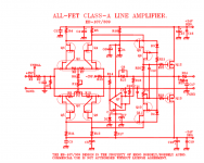
Here is an all jfet version by Borbely, ouput devices can be jfets, 216/79 mosfets, or 162/1058 depending on whether you want a small class A power amp, preamp, or buffer.
Chris, I live just south of Georgetown, and am using all Borbely jfet gain stages for phono, line stage, dac, and power amp.
Chris, I live just south of Georgetown, and am using all Borbely jfet gain stages for phono, line stage, dac, and power amp.
Attachments
Last edited:
Hi ticknpop,
Cool, I had no idea you were so close!
At some point I wouldn't mind hearing your system. Thanks for posting the diagram, but it won't open. I'll let someone know in the engine room.
-Chris
Cool, I had no idea you were so close!
At some point I wouldn't mind hearing your system. Thanks for posting the diagram, but it won't open. I'll let someone know in the engine room.
-Chris
Curl is simply wrong, Cordell, Cherry, Cambrel, Jung, Leach all think so
Otala was wrong in his analysis, Cordell proved it with hardware, amplifier
AND phase sensitive IMD measurement
for those wanting "personal narratives" Jung and Leach are especially persuasive because both initially embraced Otala's formulation and published circuits incorporating some of his ideas
But in a highly respectable bit of intellectual honesty both later published "retractions" of their endorsement of Otala's formulation, stating that on fuller analysis they both concluded that low PIM/TIM/SID can be achieved in high loop gain, "low open loop corner frequency" designs
so you are really thanking John for being wrong all these years and continuing to mislead on the issue in the face of overwhelming technical analysis, peer reviewed publications AND measured hardware
Otala was wrong in his analysis, Cordell proved it with hardware, amplifier
AND phase sensitive IMD measurement
for those wanting "personal narratives" Jung and Leach are especially persuasive because both initially embraced Otala's formulation and published circuits incorporating some of his ideas
But in a highly respectable bit of intellectual honesty both later published "retractions" of their endorsement of Otala's formulation, stating that on fuller analysis they both concluded that low PIM/TIM/SID can be achieved in high loop gain, "low open loop corner frequency" designs
Hi John,
Thank you for explaining that. I haven't worked with this configuration using J-Fets.
Quote:
Active loads usually cause increased differential phase, and a good reason for using resistors instead.
That is what I didn't know.
-Chris
so you are really thanking John for being wrong all these years and continuing to mislead on the issue in the face of overwhelming technical analysis, peer reviewed publications AND measured hardware
While not trivial measuring differential phase to a very high resolution can be done to verify John's note. I can see how an active load would have its capacitance change with voltage (typical of most semi junctions) and that can modulate phase. If you are low or out of loop gain its harder to mitigate. This would be important in an oscilloscope or video amp where gain is not unlimited. Measuring differential phase at 1 KHz would be more involved but not that difficult.
Otala was wrong in his analysis, Cordell proved it with hardware, amplifier
AND phase sensitive IMD measurement
for those wanting "personal narratives" Jung and Leach are especially persuasive because both initially embraced Otala's formulation and published circuits incorporating some of his ideas
But in a highly respectable bit of intellectual honesty both later published "retractions" of their endorsement of Otala's formulation, stating that on fuller analysis they both concluded that low PIM/TIM/SID can be achieved in high loop gain, "low open loop corner frequency" designs
so you are really thanking John for being wrong all these years and continuing to mislead on the issue in the face of overwhelming technical analysis, peer reviewed publications AND measured hardware
SID. Can you expand this one. I can't seem to get it.
- Status
- Not open for further replies.
- Home
- Member Areas
- The Lounge
- John Curl's Blowtorch preamplifier part II