I'm not a fan of RCL counter resonance networks, they may work at one amplitude and then at another they are completely off. Springs in loudspeakers are not linear and thus resonances are not stationary.
Correct. Any decent electronic filtering applied to combat electrical and mechanical resonances has to take into account the momentary voice coil temperature and the signal amplitude respectively.
This can not be done with passive RCL means.
George
Oh, please, hit the membrane of your disconnected speaker with your finger, and do the same, shortening the coil !Transient response is OK, not worsened,
Did-you tried ? You will have some surprises. Like to constat that, done in free air, to compensate the resonnance of a boomer, they still continue to gives-you a near flat impedances curve... in a vented box (bass reflex). Just you'll have to adjust the R of the RLC.I'm not a fan of RCL counter resonance networks, they may work at one amplitude and then at another they are completely off. Springs in loudspeakers are not linear and thus resonances are not stationary.
Anyway, you will have some 10% error in the impedance curve instead of 500% with no compensation!
And you can measure the difference in the response cruve even with a traditional amplifier of high damping factor.
It is about QTS.
While i'm on it, instead of stupidly gluing damping material on the walls of your enclosures, make curtains in the *middle* of each lenghs, separating the volume in 8.
Last edited:
Would you think i have not tried..?? actually we did it in the first generations of Raidho speakers.
Later we more and more look into flow damping. It does the same for the load-curve, but without the expense of creating parallel current escape paths. to our experience those circuits robs the life out of the music.
And you're right about damping on the walls of the enclosure, there's no air motion there, only pressure and that cant be damped just by making the walls soft. Cabinets need to be structured quite differently.
Last edited:
http://www.esperado.fr/temp/critique-en.htmlto our experience those circuits robs the life out of the music.
http://www.lamaisonduhautparleur.com/pdf/KIT-AERIA-SYSTEME.pdf
(Nobody payed for this review ;-)
Last edited:
CAn-you help-me a little with a link to it ?Please take a closer look at the cloth over the basket post a while back.
While i'm on it, instead of stupidly gluing damping material on the walls of your enclosures, make curtains in the *middle* of each lenghs, separating the volume in 8.
Yes Esperado. Acoustic resistance tiles placement becomes most effective where air volume velocity is maximum .
When combating internal reflections, for a go and return path btn two opposite walls, the optimum position is in the middle if one is to use the minimum amount of damping material.
Close to the walls, parallel to them, air velocity is minimum (except for the case of tangential mode reflecting waves).
George
George maybe you can explain a little more about the cloth trick you brought forward in post:
http://www.diyaudio.com/forums/loun...ch-preamplifier-part-ii-6025.html#post4193649
http://www.diyaudio.com/forums/loun...ch-preamplifier-part-ii-6025.html#post4193649
CAn-you help-me a little with a link to it ?
Michael is referring to the attachments on this post
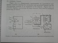
Driver’s main
George
>Edit. We cross posted. I will try to find some theoretical analysis reference to this first.
Last edited:
Tom, I recall Richard Heyser showing us his prototype of the TEF 'machine' back in the very early 70's. It was more than I could 'get a handle on' at the time, still is in how it is better than FFT. FFT is all that I have worked with, so far. Richard was WAY ahead of his time.
“Tom, I recall Richard Heyser showing us his prototype of the TEF 'machine' back in the very early 70's. It was more than I could 'get a handle on' at the time, still is in how it is better than FFT. FFT is all that I have worked with, so far. Richard was WAY ahead of his time.”
Hi John
I am envious of people like you and Doug Jones at work who actually got to talk to him and knew him personally. I feel like I know him a tiny bit having heard him once and poked around in his archives and stuff but I couldn’t agree more about him being way ahead of his time. I have a read a couple of his later unpublished papers and it is agonizing not to be able to ask what did you mean here and can I show you something?.
Your right about the tef machine, it is I think another example of narrow licensing vs broad licensing as was the Beta vs VHS situation, beta being technically superior but narrowly licensed. The process really is superior especially in noise immunity. At the early Synaudcon TEF workshops, they took 10 tef machines and mixed the outputs and fed that to a speaker and then took he microphone, split it into 10 and fed that to each tef.
The immunity was so great, all 10 tef’s could be measuring at the same time.
John, being an amplifier guy and me having been in oscilloscope / solder flux withdrawal for several years now, there is something I would like to bounce off you as a speaker guy.
Lets say an imaginary “perfect” amplifier looks like a wire with gain and very low output Resistance.
We strive to get to that low output resistance by having some raw output impedance, lowered roughly by how much negative feedback is available at that frequency.
We put a small cap in parallel with a resistor across the output and drive it with a square wave and what you see isn’t the RC droop one expects with a resistance driving a capacitance, you see ringing.
When you design a passive crossover, you can’t (or shouldn’t) look up values in a table because these assume you have a resistor terminating the network where you are dealing with a loudspeaker which only is a few places in it’s impedance looks like a resistor.
We were discussing the back emf, that velocity proportional generator voltage a permanent magnet and moving wire always and unavoidably creates. The same voltage that makes a loudspeaker driver a rather sensitive microphone. The same voltage that is fed back to the amplifier WHILE the amplifier is sending it signals.
So, what does the output end of amplifiers sound like?
Here is my idea, take an amplifier with an grounded on one side or isolated output.
Connect an 8 ohm resistor on the hot side output.
Take an amplifier you want to test, connect the free end of the resistor to the amp’s hot side and ground the input. Now, drive the first amp with your test signal or music at a safe level and measure / listen to the voltage on the output of the input grounded amplifier.
This will I would guess have the spectrum shape one has when measuring damping factor but what the amp sounds like and how much distortion there is, is another matter.
Some of what makes an amplifer “sound” may be available in I’s raw form by removing the music signal that normally accompanies it by grounding the input but requiring all the circuitry to be active fighting to keep the output voltage near zero.
The error is what appears as signal on the output.
An amplifier could be examined at different phase angles too by driving what was the grounded amp with the same test signal but shifted in phase. A 90 degree phase shift might be a good way to see what an amp sounds like at the extremes of soa and at higer levels, soa protection.
Anyway, as a cone head, “what an amplifier sounds like as a load to back emf” something I have wondered about but never got around to looking at.
Best,
Tom
still is in how it is better than FFT. FFT is all that I have worked with, so far. Richard was WAY ahead of his time.
Everything he did was described by him in all its mathematical beauty. It can all be done now in software on sampled waveforms.
Everything he did was described by him in all its mathematical beauty. It can all be done now in software on sampled waveforms.
While that is true (the TEF 20 and 25 are software based) , what isn’t equal is the noise immunity the TDS process still offers over the systems that measure impulse with a sequence.
measure impulse with a sequence.
Do you mean an impulse or the same chirp he used (IIRC)?
Thank-you George, i was searching hard in the MiiB posts.Michael is referring to the attachments on this post
Well, one ironic remark, if i like to dump the resonance and lagging (?) of a speaker, i don't like to add any charge to the way it answer to a pulse ;-)
I apologize, PMA... My recent AVC had certainly burned most of my few neurons left, i was thinking current in the sens of high impedance source, not considering the speaker in the feedback path.Oh, please, hit the membrane of your disconnected speaker with your finger, and do the same, shortening the coil !
My old attempts to servo-ed systems used a speaker with the traditional moving coil assembly in the back of the boomer, and an other one, as a captor with a little magnet, on the front side.
Last edited:
When you design a driver you always add springs and means of dynamic damping or else you would have the cone in your lab at the first transient.
if you use resistive flow damping you will be able remove some of those elastic elements as well.
Most commercial speaker units are fitted with aluminum VC-former, that is extreme dynamic damping (due to hysteresis), another very big controlling spring is the Spider, with flow damping that can be perforated to extreme degrees in order to make it softer and thus reduce the dynamic unlinearity from that element. Ofcourse drivers for this kind of flow controlled environment must be tailored to suit and it's a long an tedious process, but i am quite sure that it's possible to create something extraordinary along this route.
Sorry for the delay. I was watching the exit poles results of the national parliamentary elections here 😀>Edit. We cross posted. I will try to find some theoretical analysis reference to this first.
The most thorough technical explanation of damping through placing acoustic resistance at the rear or at the front of the speaker that I have access to, is here.
http://www.ejjordan.co.uk/PDFs/A-Cabinet-of-Reduced-Size-with-Better-Low-Frequency-Performance.pdf
Then, there is Attachment 1.
It is is a picture from page 9 of the book “Theory and Design of Loudspeaker Enclosures” by J.E. Benson.
There you see a dashed line representing an acoustic impedance rab which forms a space behind the driver marked as a compliance Co. The rab act in series with Co and both in parallel to the elements of the speaker. Also the rab provides a controlled decoupling between the compliances of the small air volume behind the speaker (Co) from the larger volume CAB of the cabin (or the room volume in case of an open baffle speaker)
It is important to minimize the mass component of the air through the resistive elements, so as these elements work as pure acoustic resistance and not as acoustic resistance in series with acoustic inductance. In more 'advanced' terms, increasing air mass inertia inside the acoustic resistance sheet, will turn the compression of the air at the rear of the driver from isothermal to adiabatic.
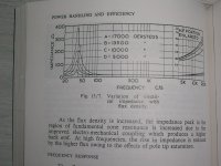
Attachment 2 shows a different way to damp the main resonance through adjusting the magnetic flux across the coil gap. It is a photo from the book “Loudspeakers” by G.A. Briggs (4th Edition 1958)
George
Attachments
Last edited:
All these methods -- damping,porting, improved materials etc etc etc.... have brought us to where we are today. It isnt nearly the same as thd reduction via amplifier/speaker which still can lower distortion even more.
I notice always a lot of talk on this forum... whereas on other forums which are more constructor and design oriented, they find out more thru SIM and prototyping, tests and measurement and building/listening. Thru thier processes, improvements are found and problems are reduced or solved. etc.
What more can we do here?
THx-RNMarsh
Oh, please, hit the membrane of your disconnected speaker with your finger, and do the same, shortening the coil !
Did-you tried ?
The test makes no sense for the current drive. The only thing that makes sense is a comparison of recorded sine bursts (on, off transients) and square waves. Recorded with microphone. Comparison of voltage drive with current drive with pre-equalization (convolution with filter impulse response, the filter is inverted impedance response).
Less talk, more doing ... as you say, 😉.I notice always a lot of talk on this forum... whereas on other forums which are more constructor and design oriented, they find out more thru SIM and prototyping, tests and measurement and building/listening. Thru thier processes, improvements are found and problems are reduced or solved. etc.
What more can we do here?
If the desired result is achieved in the real world, by accident in my case, then all the focus can be on precisely the factors that must matter, rather than theoretically relevant ones - experimenting to see which parameters are crucially important, as compared to just being intellectually satisfying to optimise.
I started off by listening, and learning to really listen - it was interesting to see how an audio friend, when I first started interacting with him, kept focusing on the things that audiophiles get all excited about - he thought he had improved the bass, say - and I said, But can't you hear how it now has an unpleasant edge to the sound!! Gradually, over time, he "got" it - and he now finds it easy to critique another enthusiast's very expensive gear, for failing to get key fundamentals right.
For me, experimenting, listening, and simulating with realistic, rather than ideal, components and surrounding environment factors have been key to making steady progress - and, most importantly, assuming nothing!! If your ears are telling you that it is wrong then it is wrong - no matter what numbers or others say, if the sound is not "working" then there is a problem ...
Do you mean an impulse or the same chirp he used (IIRC)?
Hi Scott
It is the TDS process itself. It is akin to a radio and how a radio rejects signals either side of where it’s tuned. Imagine you have a sweep generator set to sweep 1100 Hz per second from some staring to some stopping frequency. You sample the result some distance away with a microphone and multiply the microphone and test signals with a modulator / multiplier which spits out a sum and difference frequency when examined with an FFT. Throw away the sum, do an FFT of the difference and re-scale the frequency scale with distance and you can see how far away that source was , as the propagation produces a delay,the mic signal is always behind the test signal. The greater the differnce in frequency between them, the greater the time delay is implied.
Once the location in time is known, then the device is swept again over the desired bandwidth following limits described by Heyser. For this mode (TDS) , it is “as if” one had a radio and were able to track a station as it continuously changed frequency instead here, it’s the direct path signal from the loudspeaker it is tuned to and tracking.
An example of where one see’s noise issues is with the sequence systems when measuring woofers.
You can see this measuring either a sealed box which rolls off at -12 dB per octave or a vented system which rolls off at -24dB per octave. These speaker systems continue to roll off a that rate BUT often these sequence based measuring systems show “free” bass energy or even flat response some short way down from the flat part of the curve. This and other noise issues can be reduced by averaging a bunch of measurements which in programs like ARTA is easy to do at the time you take the measurement. These measurements allow the magnitude curve’s roll off to be shown properly to a lower level below the flat region. Another place noise shows up in sequence systems is at low frequencies, seen as a jagged response around the lf corner and roll off, woofers don’t do that.
When you set the mic gain properly with the TEF, it wouldn’t be unusual to see that roll off slope continue to -50 -60dB below the flat response region. The TEF platform is ancient now, the company that bought it from Tecron has not done it justice. There is a company working on software to do TDS on an Ipad but it is a year past when they thought it would be ready.
Interesting, shortly before his death approaching 30 years ago Dick Heyser who invented this system also wrote about multiplying a forward log sweep with a reversed log sweep to derive the impulse response which is the time view of magnitude and phase with all the fixed time delays removed. That is the basis of a number of other measurement systems now days like Acourate;
http://www.audiovero.de/en/acourate.php
This produces a more faithful impulse response but still has inferior noise rejection (so you measure loudspeakers in a large quiet room).
Best,
Tom
I answered-you about this 4 post before.The test makes no sense for the current drive.
- Status
- Not open for further replies.
- Home
- Member Areas
- The Lounge
- John Curl's Blowtorch preamplifier part II