www.ada-acousticdesign.de/ada_dl/AES116-final.pdf
Nothing to do with speaker distortion reduction but is consistent with this forum's A.D.D.
-RNM
Nothing to do with speaker distortion reduction but is consistent with this forum's A.D.D.
-RNM
Last edited:
I answered-you about this 4 post before.
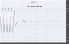
I have just made a set of new tests. Voltage drive x current drive with pre-equalization of input voltage according to speaker impedance. Square response is same in both cases. The "short and membrane tick" stigma would apply only for uncontrolled, i.e. flat voltage at the input of the V/I converter. Then the square response shape would reflect changes in frequency response due to speaker impedance curve.
Attached is sine burst turn off with both voltage and current drive.
Attachments

Last edited:
I find it quite funny that we talk distortion in the bass, by nature bass is distorted and phase shifted, it sort of goes with the long acoustic wavelengths.
Now we will sacrifice inherit linearity for a lower waveform distortion, or more specific one kind of distortion for another, less waveform distortion for more level distortion, while it may be possible for current drive to be tailored so there's a balance with the resonances inside the cabinet, but what will then happen when you place the speaker in another room and the working conditions change, so the spring on the frontside of the membrane behave different with different resonance pattern.?
My prediction is room bam boom enormous. Sorry but I don't see current drive being possible, unless you want to create a DSP based room correction monster. And to be frank I have never heard any such system sound anything but sterile cold and killing the music.
Last edited:
I agree with MiiB.
Dynamics before THD, anytime, anywhere. Better to have dynamics at the cost of some THD, as long as it's below 1% in the bass, than low THD and dead sound. Dynamics gives us life-like sound much more than a marginal gain in lower THD.
Just my 2 eurocents' worth.
Dynamics before THD, anytime, anywhere. Better to have dynamics at the cost of some THD, as long as it's below 1% in the bass, than low THD and dead sound. Dynamics gives us life-like sound much more than a marginal gain in lower THD.
Just my 2 eurocents' worth.
Why would current drive interact worse with room resonances than voltage drive? Especially if the speaker is mechanically damped rather than trying to EQ out a high-Q resonance. Whether it is damped with EMF braking or mechanically I don't see the difference where room interaction is concerned.
Why would current drive interact worse with room resonances than voltage drive? Especially if the speaker is mechanically damped rather than trying to EQ out a high-Q resonance. Whether it is damped with EMF braking or mechanically I don't see the difference where room interaction is concerned.
Yes, there is no reason why would current drive interact worse with room resonances. BTW, I am plying with room EQ as well and I can confirm there is nothing wrong with current drive.
I assume that the reason why some guys are suspicious is that the current approach goes behind routine intuition that is usually applied, rather than real results. Also some knowledge base above usual diy approach is needed, like understanding of convolution, transfer functions and relation between time and frequency domains. I understand that some guys are confused.
Normally speakers are not mechanically damped, instead resonances are used to extend the frequency response, so it extends lower, with flow-damping you sacrifice (or you need to secure low frequency output by other means ) some lower range bandwidth.
With voltage drive the speaker will be kind of self adjusting as where the resonance work the amplifier current pull is lower.
With current drive you totally lack this self-adjusting property.
So that leaves us, for current drive only with the option of damping the cone motion with other means than springs. Either by EQ or some kind of mechanical damping (that does not result in impedance bumps). But what you do on the inside of the speaker is just one side of the equation, the room interaction on the other side of membrane is also a part of the equation.
That side is btw where we are and where we listen and a resonance there will also be visible as a rise on the impedance curve and with voltage drive, the result will be less current pull and electro-mechanic force on the cone and thus will the speaker to a large degree be self aligning, Not so with current drive. you'll have room boom fantastic. OR DSP
He he, room equalization !
I noticed, when i was doing big PA for Rock'n roll concerts that each and every attempt to flatten the response curve in a concert hall on a measurement basis was a failure. I believe that it is because our brains can discriminate in a large part the original source from the room resonances. It helped me to find where the big problems were in the response curves, but the best results were done with ears.
Not to talk about violent phase turns that analog 1/3 oct. equalizers were doing at this time...
(Thanks a lot, PMA, for your curves, the suspect must be acquitted )
Last edited:
Anyway, what is really the differences between servo-ed speakers, using a separate captor to get a better control of the membrane movements and "current drive" ?
In current drive, the original signal is mixed with the ones produced by the coils movements. It seems the first solution is better, not ?
The only real benefit i can see is that we can use current drive with 'on the shelf' conventional speakers.
Because i'm not disturbed so much with the distortions at low frequencies my personal speakers can produce, because the complexity of all those stuff, i finished to give-it up.
Where it really matters for me, dynamic, mediums, treble reproduction, it seems that it is useless.
So until someone finds a better way to convert an electric signal into sound pressure that these crafts of glued cartons, magnets and moving coils, I just ... try to find the most compelling crafts...
A nice, clear and well thought out paper!
Thanks.Good paper...🙂 Nice reading
I suggest it to illustrate that the recent distortion measurements presented are not really adequate.
More complex testing is needed to flesh out what benefits (or not) are possible with loudspeaker current sensing FB.
Dan.
Thanks.
I suggest it to illustrate that the recent distortion measurements presented are not really adequate.
More complex testing is needed to flesh out what benefits (or not) are possible with loudspeaker current sensing FB.
Dan.
Well that was good inspiration then, The part about masking is particularly relevant to the question of why simple THD numbers don't tell you much.
Nonlinear Audio Distortion - Bruce Hofer, Robert Metzler
Another approach, suggested by Thiele [3] and Small [4], involves a clever choice of test frequencies
to place both even- and odd-order components near each other. The idea is to choose
the two test frequencies in almost a 3:2 frequency ratio. If they were exactly a 3:2 ratio, the second-order
and third-order products would both fall at the 1 position in frequency; i.e., for tones
of 10kHz and 15 kHz, both distortion components would fall at 5 kHz. Both components may
then be measured with a single multipole bandpass filter tuned to this frequency. To prevent possible
cancellation of the two distortion products if they should happen to be of opposite phase,
the frequencies are offset slightly. The distortion components will then be at slightly different
frequencies, yielding an unambiguous measurement.
AES - Total Difference-Frequency Distortion: Practical Measurements - Small, Richard H.
AES - High-Performance Total Difference-Frequency Distortion Meter
I don't have AES membership so can't access these articles 🙁.....hint.
Dan.
Hi Scott
It is the TDS process itself. It is akin to a radio and how a radio rejects signals either side of where it’s tuned.
Tom
Yes, You can set up a spectrum analyzer to do this with an offset in the IF. I did it to test speakers with an old HP (triple conversion, all analog, with as low as 3Hz wide crystal filter IF's IIRC). My point was in any case you capture a single signal with a mike and process it, I don't see a difference in SNR analog or digital with the SAME technique if sufficiently sampled.
Yes, You can set up a spectrum analyzer to do this with an offset in the IF. I did it to test speakers with an old HP (triple conversion, all analog, with as low as 3Hz wide crystal filter IF's IIRC). My point was in any case you capture a single signal with a mike and process it, I don't see a difference in SNR analog or digital with the SAME technique if sufficiently sampled.
Hi Scott
It may well be that under theoretical conditions, all of the approaches are equal or limited by how long the data is and S/N etc. On the other hand, I measure a lot of loudspeakers and transducers and so have a number of ways to measure.
What I can say is that using the same earthworks mic, same speaker under test, same drive amplifier, and same locations in the same room, that TDS has better noise immunity than the MLS systems, ARTA and so on.
I use ARTA often too and have found average 5 or more sequences remove some of the random noise effects, with TDS, multiple sweeps normally overlay.
I guess the only other thing I can say is that with TDS, I can measure a speaker while a vacuum cleaner is running in the room, that destroys a measurement with ARTA etc.
On the other hand, even TDS is limited in it’s reflection free zone, to be “absolutely sure” down to lower frequencies, I measure on a tower outdoors so that nothing but the speaker reaches the microphone.
The other thing is what I need is the driver’s acoustic phase as Heyser described, the sound phase relative to the input signal Voltage once all of the propagation delay is removed. Since what I am trying to do is make the drivers add coherently into one source and ideally without crossover phase shift, I also need to know how they relate to each other in time.
With TDS, this is effortless as one starts by establishing the acoustic distance which governs how much phase wrap was incurred by the distance to the microphone. From then on, everything is related to that point in time.
Best,
Tom
With TDS, this is effortless as one starts by establishing the acoustic distance which governs how much phase wrap was incurred by the distance to the microphone. From then on, everything is related to that point in time.
Best,
Tom
I guess you mis-understood my comment, I was only talking about TDS and doing it in software rather than building a specialized analog box to do it.
When I read Richard's papers I realized I could make an HP spectrum analyzer (~1980 vintage) do it and get the phase wrap you describe, etc. by offsetting the IF i.e. shifting the time window that the "radio" is looking at from the stimulus (sin sweep in frequency).
- Status
- Not open for further replies.
- Home
- Member Areas
- The Lounge
- John Curl's Blowtorch preamplifier part II