Tom, I recall Richard Heyser showing us his prototype of the TEF 'machine' back in the very early 70's. It was more than I could 'get a handle on' at the time, still is in how it is better than FFT. FFT is all that I have worked with, so far. Richard was WAY ahead of his time.
Here's a rather nice comparison video, https://www.youtube.com/watch?v=MMk_7JgEAgQ. Would be interesting to get people's reaction to this ...
They needed to be closer to "on axis" for the manger (it has dispersion issues too) and there is that distortion problem which is an issue even at 90Db @ 1m @ 200Hz. You can hear the difference in the drivers and loading.
When we were doing loudspeaker generation loss recordings at work, we had to do recordings on a tower outdoors or on a lift in the quiet warehouse to suppress reflections and room sound.
Our hearing system also involves the subconscious rejection of things it has learned are "noise" leaving you with gaps which your brain fills in, all without your knowledge.
When you listen to a loudspeaker through a good measurement mic and good headphones (in a semi anechoic or large space), you have largely bypassed the process and so the warts are more apparent.
Play back and re-record and you have a caricature of what's wrong.
This doesn't tell you what to fix but once the little wart becomes a flaming boil after a couple generations, it may help point the way to where it is.
Those who deal with electronics would probably horrified to have something so unfaithful to the signal that it makes un-listenable sound on just 2 or 3 passes.
In the old days, there was a joke that if you handed a set of detailed loudspeaker measurements to an electronics engineer and asked what he made of the data, the answer was "well that's broken what ever it is".
Just discovered a speaker related thread, and a post thereon which, yet again, perfectly describes the illusion: http://www.diyaudio.com/forums/multi-way/244508-monster-massive-22.html#post4158058 ; it also has a response by Tom. This is what occurred to me 30 years ago, with highly conventional speakers and electronics - the key difference was that my system was in a highly optimised state. This "discovery" is what has motivated me in this field, in the decades following - where I differ from most who have experienced this, is in the realisation that the effect is dependent upon overall system behaviour, rather than just a manifestation of the type of speakers - extremely efficient horns are a superb shortcut to achieving this type of sound ...
Last edited:
PMA, all new approaches are appreciated. However, we have to make our amps useful for a variety of loudspeakers and speaker types. Your method is practical only for a specific loudspeaker and not even a complete speaker system that is designed around voltage drive to get best frequency response.
Now, Richard's approach, as illustrated by davada, was used in an Audible Illusions solid state power amp that I once worked with. I didn't take it so seriously 25 years ago, when I should have, because it looks like an easy approach to improving speaker distortion. I'm sure that the amp's designer got the idea from Richard. We hope to make the successor of this amp in future, (it is already designed on the computer, and I do believe that we should retain this feature.
The Current-Mode Feedback operation has inherent qualities which would make them more effective than VFB topology with this speaker distortion reduction method..... thereby making them useful/stable with any loudspeaker driver.
VFB topology should be made universal as well if you dont get greedy with the thd reduction.... however, even 6dB is very worthwhile or reducing speaker thd by 1/2.
THx-RNMarsh
Last edited:
Richard,
Can this same effect be used on the high end, is this reduction in distortion only for the bass speaker or can the effect be shifted into the 2.5Khzand up range?
Can this same effect be used on the high end, is this reduction in distortion only for the bass speaker or can the effect be shifted into the 2.5Khzand up range?

Richard,
Can this same effect be used on the high end, is this reduction in distortion only for the bass speaker or can the effect be shifted into the 2.5Khzand up range?
Steven, IMO the distortion would be reduced at any frequency with linear current drive. Image rather than words.
Attachments
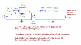
I made a model in the simulator for nonlinear suspension. It was tricky but if I have an accurate K() function for the nonlinear suspension I could plug it in.
See attachment for only one of the suspension nonlinearities that have to be modeled.
Curious about other distortion mechanisms I can try to model.
A lot of valid input here for your interesting simulation effords:
Papers
Steven, IMO the distortion would be reduced at any frequency with linear current drive. Image rather than words.
For the case that there are new participants in the current drive discussion, this is an important book, not for the conclusions it draws but for the analysis and modeling you can read in it.
http://www.amazon.com/Current-Driving-Loudspeakers-Eliminating-Distortion-Interference/dp/1450544002
George
Attachments
Does it have to be one or the other..??
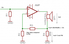
What if a CFA is made with the speaker load in parallel to the feedback resistor, and the feedback GND-resistor in series with the load GND-resistor, then you get a little expansion where load impedance is higher. This way you can retain some of the corrective action, but not throw the universal usage away.
What if a CFA is made with the speaker load in parallel to the feedback resistor, and the feedback GND-resistor in series with the load GND-resistor, then you get a little expansion where load impedance is higher. This way you can retain some of the corrective action, but not throw the universal usage away.
Does it have to be one or the other..??
What do you exactly mean like "one or the other", Michael?
Which is "one" and which is "the other"?
Last edited:
The first thing i do since decades, now, is to add a serial RLC network to any speaker i plan to use in order to compensate its impedance curve at resonnance, in // with a more traditional RC Zobel (can be more complex with Eddie Currents for tweeters ). The goal is to get a flat impedance curve equal to the DC resistance.
Under, an example of my passive filter for my medium/treeble horn (2426J JBL driver). (forget the high pass filter, the response curve correction and attenuator parts)
The listening improvement with a voltage source traditional amplifier (a CFA, of course ;-) is obvious and worth the price of the components.
Oh, it could be tried with a current drive amplifier to see if any better ?
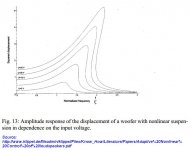
Now, if we will appreciate the reduction of distortion and that the high source impedance will excite less the membranes resonances, and character of its material, what about the transient response ?
I mean, if here, with a horn/compression high mechanical damping, we are in an ideal situation, what about the boomer ?
I mean, if here, with a horn/compression high mechanical damping, we are in an ideal situation, what about the boomer ?
VFB topology should be made universal as well if you dont get greedy with the thd reduction.... however, even 6dB is very worthwhile or reducing speaker thd by 1/2.
THx-RNMarsh
6dB makes it VERY worthwhile.
Transient response is OK, not worsened, IF you have used pre-equalization of frequency response as well. DSP on the input electrical signal. It is impossible to use the current drive without frequency equalization.
Please take a closer look at the cloth over the basket post a while back. That is in its simple form flow damping. Look at the curves and see how the resonance impedance peaks are greatly reduced
Make the cone motion critically damped by controlling the airflow and you hardly have any resonance issues, this is what we work quite intensely with at Raidho
Honestly I belive that this is a speaker design issue and not a reason to fundamentally change how amplifiers work.
I'm not a fan of RCL counter resonance networks, they may work at one amplitude and then at another they are completely off. Springs in loudspeakers are not linear and thus resonances are not stationary.
PMA I meant either current or voltage drive,
Last edited:
Play back and re-record and you have a caricature of what's wrong.
This doesn't tell you what to fix but once the little wart becomes a flaming boil after a couple generations, it may help point the way to where it is.
Those who deal with electronics would probably horrified to have something so unfaithful to the signal that it makes un-listenable sound on just 2 or 3 passes.
This is effectively convolution of system IR with itself. Any deviation from flat response in phase/frequency response becomes magnified.
A classic is square wave response; record square wave response, record response of recording played in reverse, and secondary recording typically reveals better square wave do to cancellation of phase errors.
Suitable inversion of IR leads to correction filter that when convolved with input signals yields very good waveform fidelity. With this method I've demonstrated square wave response from 10Hz to >3kHz.
I've seen your square wave responses posted for Synergy system, and have used a posted IR waveform convolved with swept square wave to confirm posted square waves, and examine frequencies where waveform breaks down.
The placement of woofers in front of tweeter provides a fixed correction for woofer group delay, and is primary reason for Synergy's excellent square wave response in certain frequency bands.
Andrew
It is impossible to use the current drive without frequency equalization.
Pavel, you know that it is possible and conditionally beneficial.
With an uncompensated (or mildly compensated) loudspeaker unit and CFA drive, the impedance increase at resonance and the gradual tilt upwards at higher freq due to driver inductance, will translate in increased acoustical output. This, may be utilized when working on a system basis (amplifier for a certain speaker) and not on a component basis (amplifier for any speaker).
George
- Status
- Not open for further replies.
- Home
- Member Areas
- The Lounge
- John Curl's Blowtorch preamplifier part II