Seeing how it appears that adding the speaker to the feedback loop works and I imagine it would work for either a VFA or CFA type amplifier circuit is it as simple as it appears to implement as it appears or are there going to be other things that need to be done to make this a working system?
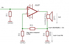
Please take into account it is a current drive. The amplifier gives
Iout = Vout/R4
Vout = (R2 + R3)/R2 x Vin
Please check the attached image.
You need to equalize frequency response, which reflects Zspeaker. Direct use is impossible.
Take a DSP, pre-equalize Vin, and you are there.
Attachments
Last edited:
Pavel,
Can I assume that you would first build the circuit and then measure the FR and then using that information implement the dsp correction or would you know the changes to the FR if the impedance curve of the speaker was already known in advance? How is this any different than having to correct the FR of an ordinary speaker in practice generally today?
ps. I know your answer will go mostly over my head, you are very detailed in your explanations but I assume others must be wondering the same thing. I always thank you for your concise explanations.
Steven
Thank you Pavel. I assumed that an active network would be used before the amplifier by you drawing. Now would there be a problem if there was a tank LCR circuit at the speaker terminals flattening the impedance curve, would that make this circuit unusable? It seems that increasing the impedance seen by the amp was part of the intention to create the current drive rather than a voltage drive.
View attachment 461252
What happens if a little series L or shunt C is added to R4 (might need to add mirroring series L or shunt C to R2 to preserve FR) ?.
Ditto series RLC and R//L//C for R2 and R4 ?.
Dan.
😎🙂
Sorry for delay -- time zone difference.
THx-RNMarsh
Last edited:
Please take into account it is a current drive. The amplifier gives
Iout = Vout/R4
Vout = (R2 + R3)/R2 x Vin
Please check the attached image.
You need to equalize frequency response, which reflects Zspeaker. Direct use is impossible.
Take a DSP, pre-equalize Vin, and you are there.
You could also replace R3 with an active circuit..... ?
THx-RNMarsh
Richard,
I tried it and it works, in the bass area. The simple V/I amplifier based on old improved Sinclair Z30 (long live old sir Clive), as per attached drawing. Shown as as well distortions with voltage and current drive. It is not only limited to resonance peak, but it works in the area of frequencies below some 100Hz.
Regards,
Pavel
Hi
Keep in mind this is old ground, back emf based systems were used for control way before in loudspeakers and even at that with Tube amplifiers in the 40’s and 50’s before we adopted the “voltage source” as standard.
If you’re serious about this pursuit, I would offer first that simply raising the amplifiers Voltage swing via an added resistor can reduce it’s distortion so one must draw conclusions cautiously.
Also, fwiw, above the low frequency end, the Voltage across the moving part or gyrator is small and falls by half each octave one goes up in frequency. What that means is for all practical purposes, it already IS driven by a current source (I = input V / Rdc + moving impedance/back emf). As the back emf falls the effect of it falls.
What I was trying to explain earlier is that the back emf is a very usable velocity sensor but the problem is, unlike a drone coil wound along side, the driven coil’s terminal voltage is both the back emf AND the voltage cause by the current across Rdc.
If one senses the output current AND then ADDS some of that back in as POSITIVE feedback, then (at null) one is adding an extra voltage to the driver, proportional to the current so that one achieves a Velocity mode of operation.
This is FAR more than a high damping factor, this is like multiplying the size of the magnet (not in power sensitivity but in response shape).
Consider that your amplifier is separated from the part that moves that converts power into motion and sound by a simple resistor.
That is the resistance of the wire in your voice coil. When you tap on a woofer outside the cabinet you hear in “boing” or ringing, the free air resonant frequency damped by the mechanical losses which comprise the Qm.
Short the terminals out and now tap the cone and its VERY different, “dead”, damped by electromagnetic damping or Qe. That “shorted “damping is actually the back emf caused by motion across the resistance of the wire.
Put a resistor equal to the Rdc in series and you see it is a little less dead but still very damped.
When you short the speaker with an alligator clip or penny, you have essentially an infinitely high damping factor, when you add a resistor equal to the Rdc, you have a DF of 1.
I did a much more thorough job explain this stuff in the 5th edition of “Handbook for Sound Engineers” if interested.
When you have a negative impedance source, and you tap the cone, you now observe it is even more stiff and if you push, it fights back and tries to retain the original position.
THIS is when you have real motional feedback and how one can reduce the distortion at the lowest frequencies where distortion is both most audible and most loudly produced by loudspeakers.
In the 80’s I was working developing sound sources for acoustic levitation and made an amplifier which went a step further in that it could present a conjugate impedance to the source, if the load was capacitive, it was inductive and so on. As this worked on the Servodrive subwoofers my boss let me work on in my spare time, I tried to apply for a patent on it but searching now, I don’t see it now.
I did find a video of those levitation sources (21Khz up to 168dB) in action;
https://www.youtube.com/watch?v=669AcEBpdsY
What I remember from the old days was it was Norelco / Phillips that had an early product using back emf feedback (current).
While many old Tube amps had this negative impedance ability, I am not sure many thought about distortion because going to full Velocity requires you to eq your low end back up. Velocity is a +6dB per octave rising slope which gives one very tight bass or very anemic low end, depending one ones taste. What gives a small direct radiator flat response (where K<<1) is an acceleration response and the cure is obvious. This is why the Crown delta Omega didn't fly.
Note this circuit, not what’s used but what the current feed back does, it is positive current feedback which produces a negative output impedance.
Motional feed back amplifier - Electronic Circuits and Diagram-Electronics Projects and Design
I found it necessary to use an rc low pass filter on the input of the power amp to allow more –fb at lower frequencies (that old Bode criteria).
What you will find as you make the impedance more negative is that adding a tiny L in series with your small current sense resistor, making it more closely emulate your driver’s Rdc+Le series elements will help. Ultimately you reach a point where it begins to squeal or squeals on audio peaks and you have now gone a bit past what you can fix this way.
The biggest drawback is that what might have been flat bass response is now distinctly rolled off, -6dB per octave but you can fix that and distortion will be lower.
The next fly in the ointment is that once Rdc starts changing, your added control starts falling apart. With woofer modern voice coils that can exceed 300C, power compression makes modern drivers not quite indestructible but now one must remember that the onset of power compression is seen between 1/10 and 1/6 of a drivers rated power so think big.
Best
Tom Danley
Danley Sound Labs
Seeing how it appears that adding the speaker to the feedback loop works and I imagine it would work for either a VFA or CFA type amplifier circuit is it as simple as it appears to implement as it appears or are there going to be other things that need to be done to make this a working system? Can I assume that this will work the same with a discrete amplifier design as well as an opamp based design? This looks like a worthwhile thing to do in something like the integrated self powered speaker that I am working on.
Now we are cooking ! 🙂 And thank you Danley for closing some of the information gaps. Everyone who designs amplifiers and who cares about the High-End sound goals should be doing this and not leaving it all up the driver designers.
-RNM
Last edited:
Please take into account it is a current drive. The amplifier gives
Iout = Vout/R4
Vout = (R2 + R3)/R2 x Vin
Please check the attached image.
You need to equalize frequency response, which reflects Zspeaker. Direct use is impossible.
Take a DSP, pre-equalize Vin, and you are there.
Pavel can you try this variant here?
Attachments
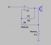
PMA's method with the 6.8R resistor should work with almost any power amp, I think. with other methods there may be stability issues.
If R4 is inductive, it will probably improve EQ because the voice coil is inductive as well. Regardless of current drive or voltage drive, we want the voltage across the speaker to be flat with frequency. So the inductance of R4 is probably not such a bad thing.
If R4 is inductive, it will probably improve EQ because the voice coil is inductive as well. Regardless of current drive or voltage drive, we want the voltage across the speaker to be flat with frequency. So the inductance of R4 is probably not such a bad thing.
Davada, that is a hybrid current and voltage drive, IE not indefinite impedance. It's like using a 100R resistor instead of a 10k resistor.
I believe in active crossover + pre-equalization before Vin as almost perfect method. We need some more headroom for extended voltage swing, compared to standard amplifier. But we are able to get up to 10x lower distortion even with a simple amplifier. I understand this will not be appreciated by conservative school of designers.
Davada, that is a hybrid current and voltage drive, IE not indefinite impedance. It's like using a 100R resistor instead of a 10k resistor.
Yes it is a a hybrid current and voltage drive. I used this circuit some 12 years ago and it worked very well but I didn't do any analysis on it at the time. It's easy to set up and would be interesting to see some comparative results.
PMA, all new approaches are appreciated. However, we have to make our amps useful for a variety of loudspeakers and speaker types. Your method is practical only for a specific loudspeaker and not even a complete speaker system that is designed around voltage drive to get best frequency response.
Now, Richard's approach, as illustrated by davada, was used in an Audible Illusions solid state power amp that I once worked with. I didn't take it so seriously 25 years ago, when I should have, because it looks like an easy approach to improving speaker distortion. I'm sure that the amp's designer got the idea from Richard. We hope to make the successor of this amp in future, (it is already designed on the computer, and I do believe that we should retain this feature.
Now, Richard's approach, as illustrated by davada, was used in an Audible Illusions solid state power amp that I once worked with. I didn't take it so seriously 25 years ago, when I should have, because it looks like an easy approach to improving speaker distortion. I'm sure that the amp's designer got the idea from Richard. We hope to make the successor of this amp in future, (it is already designed on the computer, and I do believe that we should retain this feature.
If one senses the output current AND then ADDS some of that back in as POSITIVE feedback, then (at null) one is adding an extra voltage to the driver, proportional to the current so that one achieves a Velocity mode of operation....
When you have a negative impedance source, and you tap the cone, you now observe it is even more stiff and if you push, it fights back and tries to retain the original position.
THIS is when you have real motional feedback and how one can reduce the distortion at the lowest frequencies where distortion is both most audible and most loudly produced by loudspeakers.
My original point, eloquently put.
😎
John,
Of course you are tight that most amplifiers are not going to be designed around a specific speaker and you do have to make your designs work with as many speakers as possible. On the other hand when I first built my prototype speakers which were made as small studio monitors the engineer who used them to mix down some movie soundtracks and music his initial response was great but he was concerned that an unpowered speaker would sound different in every studio if a different amp was used in each instance. This led me to going with an active amplifier built with the speaker and I have since decided that I would not limit the use to studio work only but make if available to consumers.
My current thinking is that I will use a commercialized version of one of the amplifiers being developed on the Slewmastr CFA vs VFA thread. I am leaning to one of the current feedback topologies and that would seem to be a perfect place to implement the speaker into the feedback loop with the current driven amplifier. Does anyone see a problem with this approach? There will be active xo's before the bi-amp speaker system and adding FR correction was already the plan.
I have designed several combined active Xover and 2 or 3 way actively driven designs. It is the RIGHT way to do it, but it is limited to one design only.
...... I am tip-toeing out the back door now...... hope this can become a new thread like CFA did and turn in some great new ideas and designs with sim and build analysis. I'll follow with my usual input here and there.
Its high time amp designers helped us all get lower speaker distortion --- Someday (soon, I hope, cause I cant wait another 30 years for this to take hold) loudspeaker system reviews will start including speaker distortion plots.
"It just keeps getting better" 🙂
THx-RNMarsh
Its high time amp designers helped us all get lower speaker distortion --- Someday (soon, I hope, cause I cant wait another 30 years for this to take hold) loudspeaker system reviews will start including speaker distortion plots.
"It just keeps getting better" 🙂
THx-RNMarsh
Last edited:
...... I am tip-toeing out the back door now...... hope this can become a new thread like CFA did and turn in some great new ideas and designs with sim and build analysis. I'll follow with my usual input here and there.
Its high time amp designers helped us all get lower speaker distortion --- Someday (soon, I hope, cause I cant wait another 30 years for this to take hold) loudspeaker system reviews will start including speaker distortion plots.
"It just keeps getting better" 🙂
THx-RNMarsh
Do you really think this matters in the long run? Folks have toyed with this for decades, speakers are designed for ideal voltage source amplifiers I don't see any change coming soon. The auxiliary issues require some user intervention, I see this lack of plug and play a show stopper. Besides the point I don't see the THD per se as an issue.
- Status
- Not open for further replies.
- Home
- Member Areas
- The Lounge
- John Curl's Blowtorch preamplifier part II