Mine was three stacked foil capacitors in series.
Of course if you have a few spare capacitors of your design...
Of course if you have a few spare capacitors of your design...
Hmmm. In physics capacitance is defined by:
i=C dv/ct
Which defines what makes for a linear capacitor. So long as C (as defined) doesn't change, the cap is linear, and no intermodulation can occur. If some intermodulation is observed, then C must not be a constant.
A common model we use for some physical caps is that there is a voltage coefficient e.g.:
Actual instantaneous C = (C value with no volts) x (1 + (voltage coefficient x instantaneous applied volts)).
In other words, C instantaneously varies according to voltage. In that model it doesn't matter how many signals or the waveshape because only instantaneous volts matters (that is to say, it doesn't matter how that instantaneous voltage was arrived at, or how it is changing over time as far as calculating C goes).
In reality, that model may be an approximation in that a simple voltage coefficient multiplier doesn't perfectly give the measured shape of the variation in C with voltage, but maybe close enough for most purposes. A graph of C verses V would be another way to express it, whatever that curve happens to be. Anyway, in that case there is both THD and IMD.
May I ask, are we in agreement for all these things? Or, is there something I'm missing?
EDIT: Sorry, I have been editing some of the above in an effort to improve clarity.
Last edited:
The EI curve may be changing, but I am just refering to an EI plot that is not a straight line. You seem to understand anything but a straight line produces IM.
The arguement Scott was trying to make is that there is only phase shift of a sine wave due to the TC network and the low frequency may be attenuated and phase shifted but the signals still algebraicly add. Mine is that higher voltages increase the current and decrease the charging time. So that when the two signals combine there will be changes in the low frequency charge rate that occur at the higher frequencies rate. So there should be some intermodulation.
Ed your a smart guy, if this observation is based on even "ideal" in every way capacitors you should be able to solve the simple R/C circuit by inspection with Laplace transforms and 3 sine stimulus and show us the IM. 🙄
If you are lazy you could use SPICE. I'm short computer resources right now, but I'm sure your circuit in post #99871 shows nothing. So what's missing or what are you really talking about?
Ed also please stop saying it's just me, when gerhard and jcx both disagree with much of these lines of reasoning. Any change of output with level that's not a simple factor would deny superposition unless of course the components are non-linear themselves. Ed as a refresher, superposition in a linear time invariant system states that the output of the system is the sum of the outputs with each stimulus applied independently.
Last edited:
I think C Vcoeff has been mentioned - I don't see a necesssary link to DA but a correlation may exist in a class like plastics with polar groups - Mylar, PEN, Polycarbonate, PPS
that any such correlation gives any info about Al electorlytics seems unlikely
that any such correlation gives any info about Al electorlytics seems unlikely
Probably not going to make things better that way. Hasn't been working has it?
What else can I do? Ed has reduced his hypothesis to a very simple example, three components. What do you think, is the intent that R and C are ideal and invariant constants for this test or is something missing? This of course would mean your $400 Teflon caps have the same IM and of course why hasn't anyone else noticed it?
I think C Vcoeff has been mentioned
Mr. Marsh - OK yes, any time you develop a voltage across the cap, you get distortion.
Mr. Simon - I do, you do, but there are a lot of folks arguing you don't with perfect capacitors.
Ed is not talking about waveform envelope aberration but IM i.e. new frequencies.
The EI curve may be changing, but I am just refering to an EI plot that is not a straight line. You seem to understand anything but a straight line produces IM.
JCX
In your simulation I thought you used two sines for a stimulus and had a difference sine in the output. Did I mis-remember or mis-read it?
Scott
As shown before non-ideal capacitors do much worse. So better dielectrics do make better capacitors.
M4
Slight disagreement, C is defined as C = q/V. The first derivative yields
C dv/dt + V dc/dt = dq/dt = i. As mentioned many times before. It is when you assume that Delta C is zero your modeling goes wrong in somes cases. Delta C is minimized by using better dielectrics and higher voltage ratings. Doing a Laplacian S plane transform ignores Delta C as does the other math cited.
Last edited:
What else can I do? Ed has reduced his hypothesis to a very simple example, three components. What do you think, is the intent that R and C are ideal and invariant constants for this test or is something missing? This of course would mean your $400 Teflon caps have the same IM and of course why hasn't anyone else noticed it?
I asked to see the results with a short in place of the capacitor. Could be some apparatus issue. Why don't we see what we get. Could be useful information for future testing with the same equipment. Or maybe the cap is less linear than we expect, OTOH IIRC some caps have been measured as very linear.
Thing is instead of putting energy in a fight, why don't we put the same energy working cooperatively to some mutual understanding. It may or may not work out, but at least there is a chance for a good outcome, or at least maybe something different from the usual. Can't say, haven't tried it.
As shown before non-ideal capacitors do much worse. So better dielectrics do make better capacitors.
Doing a Laplacian S plane transform ignores Delta C as does the other math cited.
Ed are you backtracking or standing by this (perfect has only one meaning)?
but there are a lot of folks arguing you don't with perfect capacitors.
BTW SPICE has provision for for all the non-idealities (but they have to exist) it's still just differential equations but SPICE does not have to solve them in closed form.
Last edited:
C is defined as C = q/V. The first derivative yields
C dv/dt + V dc/dt = dq/dt = i.
That works. For a capacitor to be linear, C has to be a constant, while Q and V are variables. Otherwise if C is allowed to change that makes it a nonlinear C and THD and IMD will result.
It is when you assume that Delta C is zero your modeling goes wrong in somes cases. Delta C is minimized by using better dielectrics and higher voltage ratings.
Sure. We are talking about a variation in C that makes it nonlinear. Please correct me if we understand that differently.
Also, because you showed some data that was unexpected by some folks, nothing wrong with then showing the result with a short circuit, with the best cap you can find, maybe a worse one than you showed before, etc. Create some context to interpret the significance of the results and also to help people feel comfortable with measurement equipment, methodology, etc. We are all humans, we need to have enough facts to form our own opinions and conclusions. People often don't form beliefs just because an authority figure tells them to. You know.
Last edited:
M4
You've got it. A perfect capacitor follows the complete mathematical model and can be nonlinear and still follow the model. All real capacitors of course deviate from the model and that requires additional manipulation to predict results. However in almost all cases close enough is fine. It is when you redefine capacitance that we disagree.
You've got it. A perfect capacitor follows the complete mathematical model and can be nonlinear and still follow the model. All real capacitors of course deviate from the model and that requires additional manipulation to predict results. However in almost all cases close enough is fine. It is when you redefine capacitance that we disagree.
Ed are you backtracking...
Nothing wrong with reconsidering things and revising beliefs in the light of new information, new thinking, etc.
The word backtracking has negative connotations, probably not helpful.
M4
You've got it. A perfect capacitor follows the complete mathematical model and can be nonlinear and still follow the model. All real capacitors of course deviate from the model and that requires additional manipulation to predict results. However in almost all cases close enough is fine. It is when you redefine capacitance that we disagree.
No, not by "engineering terms" of linearity. A perfect capacitor is perfectly linear. Sorry.
At -120 dB, this looks much more likely an instrumentation error, unless you're using truly junky film caps, which doesn't seem the part.
Scott
Can we agree a perfect capacitor follows C = q/V ?
Why was that ever an issue? There remains, in your picture are C and R constants i.e. perfect with respect to predicting the expected output? If they are there is no mechanism to create IM (new frequencies) and you can only get the 3 sines out with some change of magnitude and phase. That is the trivial Laplace transform does give the exact solution.
M4
You've got it. A perfect capacitor follows the complete mathematical model...
....However in almost all cases close enough is fine. It is when you redefine capacitance that we disagree.
I think we mostly agree. The only difference might be a misunderstanding between us due to shorthand terminology. Engineers are trained to use and to think in terms of idealized linear models. We define a type of conceptual ideal capacitor which is a constant C in our linear mathematics. We just take it for granted when we talk we mean idealized components unless we specify otherwise.
On the other hand, you seem to be using a real capacitor as the default unless you specify otherwise.
There are good reasons that engineers do it the way they do, but we need to make sure we both understand what we mean when we talk. Try to figure out how to use the same language or ask questions politely when needed. And get polite answers in return.
Scott
Can we agree a perfect capacitor follows C = q/V ?
No, actually we can't. Sorry. There is no EE definition for a perfect capacitor. Only a definition for an ideal capacitor. Perfect and ideal mean two different things in this context.
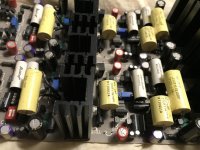
Direct coupled Borbely jfet phono stage with all Relcap films - 1% teflon RIAA caps, polystyrene servos, teflon bias bypass, and Blackgate electrolytics. And glue to hold the oversize parts in place. Teflon pc board. 90 ma output stage bias.
Front end is 4 x 2SK147 and 4 x 2SJ72 jfets
Front end is 4 x 2SK147 and 4 x 2SJ72 jfets
Attachments
Last edited:
While we're at it, we shouldn't freely mix up the definition of capacitance, with the definition of capacitor. We can all agree on some definition of capacitance. The issue seems to be with capacitor.
To restate in one place, to an EE a capacitor by default refers to a mathematically ideal conceptual model of a capacitor. Same for resistors, inductors, voltage and current sources, switches, maybe something I missed. Ideal capacitors have constant C, and they don't distort or create new frequencies.
Why do it that way? Because it works best with the math we have, and with well developed existing ways to think about electrical stuff. Powerful tools, and we can't do anywhere nearly as much or as well with any other system presently available.
- Status
- Not open for further replies.
- Home
- Member Areas
- The Lounge
- John Curl's Blowtorch preamplifier part II