Provided its frequency is low enough, a steady state square wave input can excite transient ringing in an RLC circuit, at a frequency that is independent of the square wave's fundamental frequency or odd harmonics.
Before you go too far you should compute the spectrum of a damped ringing initiated at exactly 500us intervals (for 1kHz in for instance).
In the case of when you first turn on the square wave generator, you can calculate time time domain response by modeling the waveform as a series of steps adding up to a square waveform lasting for as long as you want. The ringing you observe in this transient case should be the same as you calculate, with no mystery new frequency production. It is completely linear.
Last edited:
Before you go too far you should compute the spectrum of a damped ringing initiated at exactly 500us intervals (for 1kHz in for instance).
The forced response certainly responds to the input frequency by definition, but the natural response (also called the zero input response) does not.
The steady state response only contains harmonics of the input and a single transient excitation of a resonant network does not contain only the fundamental resonant frequency. Standard Fourier analysis and the convolution theorem give the correct answer.
http://home.agh.edu.pl/~kwant/wordpress/wp-content/uploads/PLC_Lecture_7.pdf
http://home.agh.edu.pl/~kwant/wordpress/wp-content/uploads/PLC_Lecture_7.pdf
The forced response certainly responds to the input frequency by definition, but the natural response (also called the zero input response) does not.
It will have less than infinite Q, meaning it has some ability to store and release energy at other than f0.
Once in the steady state it will be running at the forced frequency and its harmonics and off of its natural center frequency.
In the transient condition, it will have an exponential envelope converging on the steady state case.
It's linear. There is nothing that requires nonlinear modeling to explain.
Scott is correct, any method you use to calculate it you get the same answer (because it's linear).
Last edited:
Ed you just posted a picture claiming 0.1% non-linearity of just resistors, that's all I was referring to. The idea here is to help others understand the issue not confuse them. The linear/linearity discussion is full of confusers, the fact that R/C charging currents and voltages are exponentials and not straight lines has absolutely nothing to do with when and where standard linear systems theory does or does not apply. Put everything down in a book "The Ed Simon View of how all Things Electronic Work" first.
Scott,
The problem is clearly yours. I made it clear that I was showing non linear or non ohmic resistors. That is because such resistors can be useful. But somehow you jump to your conclusions based on pretty much nothing to do with the topic or material presented.
Do you know why or when nonlinear resistance is useful?
Can you identify the significant different charachteristics of the two samples presented?
Obviously not, yet you jump to the conclusion that the point had something to do with the application of small resistors in a cell phone!!!
So do enlighten me why would a pair of seemingly different deliberately different resistors and the distortion results be shown? (In your special view of the world.)
Scott was doing just fine until his last sentence. Why not point out it didn't add anything useful or something instead of attacking back harder?
To the audience out here, I would say it looks like the problem in not clearly one person's.
The acrimonious debate aspect to of some of it probably leads nowhere useful or constructive.
What Daniel Kahneman used to do when somebody strongly disagreed with him was to offer to work on a mutual research project with the other person to see where some agreement could be found. A paper he published with his biggest critic, Gary Klein, was entitled, "A Failure to Disagree." When it came down to the facts, they didn't know it at first, but it turned they did agree. Where they always differed were in their personalities. They viewed the world from two very different emotional perspectives, and as it turned out that was the underlying basis for the nature of the earlier criticism and disagreement. They never became close friends, but they agreed to disagree more civilly in the future, and they did.
Not expecting a mutual project in this case, but Kahneman's wisdom in handling the situation might at least illustrate these situations don't have to have exactly one winner and one loser.
Last edited by a moderator:
Sorry for interrupting but keep chatting away as we are only 0.153234 percent away from 100,000 posts.
I'm sure we want to get there before the new site is up and running. Current post count #99847.
before I for get any one have a spare hard copy of the Nation Semiconductor Linear Applications Handbook? PM me with details, that includes any of the AD handbooks too. Looking for more and I'm not an insurance company either.
OK.
Look, if a capacitor has any Dielectric Absorption (DA) it can be modeled as Dow first proposed -- a number of parallel branches of series RC.
That also means that on charge. discharge there is more than one exponential discharge. If you are careful, this can be measured and shown but also now easily demonstrated in CAD software.
Multiple exponential components will distort the perfect -- single exponential slope - The DA model elements have longer time constants and smaller peak values. But if you superimpose a perfect exponential slope with a slope from added exponentials, the waveform is different -- it is distorted.
I wrote a short article years ago called "How linear signals can sound non-linear". This is one way.... changing the waveform shape. To some degree, changing the waveform shape will sound different in a comparison.
Here is a high quality film cap with low DA. If only the esr was present the shape will have a slight atten of the peak but same shape. The perfect one (red) and the one with small amount of DA (green)... Result is peak amplitude is reduced by almost 0.1dB and the freq or time constant longer and 'fatter' .
This would be hard to detect by listening. But several such caps removed in a system/amp (DC-coupled) and even this very good cap will be detectable.
Of course, higher DA caps (polar) are much worse.... greater waveform change. Removing just one can be detected.
An exponential upon several added exponentials gives more exaggerated waveform change/result with larger DA R-C equivalent values.

THx-RNMarsh
Look, if a capacitor has any Dielectric Absorption (DA) it can be modeled as Dow first proposed -- a number of parallel branches of series RC.
That also means that on charge. discharge there is more than one exponential discharge. If you are careful, this can be measured and shown but also now easily demonstrated in CAD software.
Multiple exponential components will distort the perfect -- single exponential slope - The DA model elements have longer time constants and smaller peak values. But if you superimpose a perfect exponential slope with a slope from added exponentials, the waveform is different -- it is distorted.
I wrote a short article years ago called "How linear signals can sound non-linear". This is one way.... changing the waveform shape. To some degree, changing the waveform shape will sound different in a comparison.
Here is a high quality film cap with low DA. If only the esr was present the shape will have a slight atten of the peak but same shape. The perfect one (red) and the one with small amount of DA (green)... Result is peak amplitude is reduced by almost 0.1dB and the freq or time constant longer and 'fatter' .
This would be hard to detect by listening. But several such caps removed in a system/amp (DC-coupled) and even this very good cap will be detectable.
Of course, higher DA caps (polar) are much worse.... greater waveform change. Removing just one can be detected.
An exponential upon several added exponentials gives more exaggerated waveform change/result with larger DA R-C equivalent values.
THx-RNMarsh
Last edited:
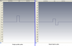
This is the FFT spectrum of a single positive pulse and of a single bipolar pulse
(I was doing some work on vinyl scratches, this may be useful here)
George
(I was doing some work on vinyl scratches, this may be useful here)
George
Attachments
kinda sorta on track Wilson Audiophile Recordings Series Reissues From Analogue Productions | Analog Planet
Yup they are re-issuing the Wilson recordings done on JC's Ultramaster on vinyl. What's not clear is if Dave let the fabled tape machine out of his house, as the SACD transfers were done in his living room!
Edit: some pics of the beast in case anyone is interested Studer UltraMaster
Yup they are re-issuing the Wilson recordings done on JC's Ultramaster on vinyl. What's not clear is if Dave let the fabled tape machine out of his house, as the SACD transfers were done in his living room!
Edit: some pics of the beast in case anyone is interested Studer UltraMaster
Last edited:
This here are the [about] cheapest relays that DigiKey has in stock and that may be usable in audio amplifiers Vdc>=100V Adc>=10A.
Electronic Components and Parts Search | DigiKey Electronics
And some data points for the most expensive one in that list (26 Euro)
http://www.te.com/commerce/Document...es_relay_datasheet&DocType=DS&DocLang=English
Rated voltage 150VDC
Rated current 10A
Contact material AgCdO AgSnOInO
Min. recommended contact load 300mA, 12VDC
Bounce time max. 17ms
The minimum contact load of 300mA can not be guarantied (in audio 🙂), but the fact that there is a minimum may indicate non-linear behavior.
The bounce time of 17ms will generate sparks for 17ms, I do not think this is a desirable feature.
The datasheet (for as far as I can see) gives no contact resistance and voltage-drop specifications, but (considering its price) I do think these will be worst than the for the previously mentioned relay (see quoted message).
All in all I can not see how one would create the best amplifier one can make and then destroy it all with one of these relays.
Why where actual relays and relay data not considered in the earlier posts?
P.s.
Silver Cadmium Oxide AgCdO
More resistant to welding at high switching current "peaks" so is used for high AC loads. Not recommended for strong DC breaking arcs because of the wear this creates.
Silver Tin Indium AgSnOinO
Similar to Silver Tin Oxide but more resistant to inrush.
Relay Contact Materials – Electronic Product Design
These are the only relays, that I could [quickly] find in the DigiKey catalog, dependable breaking more than 10A at 150Vdc (or higher), prices are 100 Euro's and up.
Electronic Components and Parts Search | DigiKey Electronics
In my opinion this is what you need to emergency-break an amplifier output.
It still is slow introduces many unwanted contact points in the amplifier output circuit.
http://omronfs.omron.com/en_US/ecb/products/pdf/en-g9eb.pdf
Contact resistance *1 30 mΩ max.
Contact voltage drop 0.1 V max. (for a carry current of 25 A)
Operate time 30 ms max.
Last edited:
My personal amp (DIY, CFA, MOSFET powered) use (big) relais. It is 30 years old. Recaped (lot of differences ;-).All in all I can not see how one would create the best amplifier one can make and then destroy it all with one of these relays.
Tried to short the relais to listen to the difference. Cannot hear any difference.
Last edited:
When playing any of my SS amps which have relays in the output, I always turn the volume down before powering off, and wait until I hear the relay pull in after powering up, before turning the volume up. This way, there can be no peak transients at contact open or closure time, so no arcing. The signal only sees closed contacts.
That's all well, but a customer will not exhibit this careful behavior 🙂 and it does not solve any possibly non linear behavior of the relay contacts.
Also, adding 30mOhm to a amplifier with a possibly lower output impedance is silly.
Also, adding 30mOhm to a amplifier with a possibly lower output impedance is silly.
My personal amp (DIY, CFA, MOSFET powered) use (big) relais. It is 30 years old. Recaped (lot of differences ;-).
Tried to short the relais to listen to the difference. Cannot hear any difference.
I think my statement ('destroy it all') was a bit exaggerated 🙂
> Tried to short the relais to listen to the difference. Cannot hear any difference
Maybe you where just lucky.
Lucky ? I don't think so. I used this amp (and its brothers) during 5 years in hazardous professional situations. Some short circuits on the speaker's lines at full power. The protection saved my life several time, because all the Hitachi power devices are still up and running ;-).I think my statement ('destroy it all') was a bit exaggerated :
> Tried to short the relais to listen to the difference. Cannot hear any difference
Maybe you where just lucky.
And, if you want to protect your relay from having to cut high A or V , it is easy to add a little mosfet relay that cut the input signal or short-it to the ground.
They are fast enough to bring the output to 0V before any mechanical relay begin to move. So the relay will have only to deal with the speakers back emf in the worst case.
And if you are afraid of this, you can add a delay to the big relay when power off.
But, as I said, I see no need in real world with a good relay, using 2 contacts in //.
In this matter, as well as the question of Caps VS servos, I stay in the "subjectivist" camp ;-)Lucky ? I don't think so.
It is so easy to compare in real situation. I mean, listening to music.
If I can feel a *real* difference, I will chose the best solution. If I cannot, the simplest.
The minimum contact load of 300mA can not be guarantied, but the fact that there is a minimum may indicate non-linear behavior.
Silver oxide material relay contacts should be avoided for audio. It is well known by relay manufacturers that silver oxide has nonlinear breakdown resistance when the contacts are closed. It takes some level of current density to revert it into a better conducting state. It is normally used in high energy contactors because of its resilience and recovery properties after arcing.
Although I don't have a reference link for the above, many years ago I looked up all the information I could on contact materials for a low level signal project I was working on. Things like gold and palladium (IIRC) are best for linearity and low contact resistance, but worst for pitting and damage from switching moderate to high currents. For my particular purposes, I couldn't find any commercially available small signal relays that worked without some degree of inconsistent charge release due to small wiping action when opening. Found that Keithley had some reed switches used for resetting integrators in their Model 616 (?) electrometers that worked great, so I ordered a few dozen from their spare parts supply service.
Based on all the above, the idea of sequenced contacts using gold and tungsten as the contact materials sounds like a good solution.
Last edited:
Jan already mentioned this relay as suitable if he missed it Toroidal Transformer Amplimo - toroidal-transformer.com
- Status
- Not open for further replies.
- Home
- Member Areas
- The Lounge
- John Curl's Blowtorch preamplifier part II