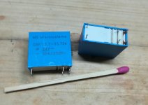
Right, the Amplimo speaker relays are the ones using sequenced tungsten and gold.
Amplimo transformers LSP-RELAY Amplimo loudspeaker relay 24V | Loudspeaker freaks
Loudspeaker relay 24V LR-24 Amplimo
Amplimo transformers LSP-RELAY Amplimo loudspeaker relay 24V | Loudspeaker freaks
Loudspeaker relay 24V LR-24 Amplimo
Last edited:
Jan already mentioned this relay as suitable if he missed it Toroidal Transformer Amplimo - toroidal-transformer.com
This particular relay looks like 2-3A/contact. I do not think it is enough for a power amp.
+1This particular relay looks like 2-3A/contact. I do not think it is enough for a power amp.
Even the pins look too thin.
Last edited:
+1
Even the pins look too thin.
Only way to know for sure would be to buy one, take some measurements, cut it open and have a look, etc.
BTW, they claim the contacts are rated for 100A, and suggest for use in amplifiers up to 500W:
-----------------------------------------------------------
"It contains a tungsten leading contact which can switch 100A (at 50V) loudspeaker current. After closing, this contact is bridged by a gold plated silver contact, giving negligible contact resistance even at small currents.
Coil voltage 24VDC nominal, at 70°C
20.4V to 33.5V
Coil resistance 900 ohm
Ambient temperature 20 to 70°C
Convenient for power amplifiers of 5 to 500W"
-----------------------------------------------------------
Last edited:
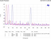
Three more runs. 24, 48 & 96 hertz through a .33 uF capacitor into a 10,000 ohm load. Note levels of harmonics and IM products.
Can you make a scketch of test setup for me to try same tests?
------------------------
Relay contacts --
Notice I had said hard gold over silver. hard gold does not wear down easily. There are also gold alloys. but hardening gold only takes a small amount of arsenic molecules to dope the gold and harden it.
THx-RNMarsh
Last edited:
Signal generator through capacitor into 10K resistor. Inject through capacitor and output across resistor.
Right, the Amplimo speaker relays are the ones using sequenced tungsten and gold.
Amplimo transformers LSP-RELAY Amplimo loudspeaker relay 24V | Loudspeaker freaks
Loudspeaker relay 24V LR-24 Amplimo
thank you, I thought these kind of relays are not made anymore.
Like this relay made for flourescent tube switching I bought years ago. It is supposed to have first make/last break tungsten contacts followed by silver/cadmiumoxide contacts:
Attachments
Jan already mentioned this relay as suitable if he missed it Toroidal Transformer Amplimo - toroidal-transformer.com
I know, and I would never use it ... 🙂 but I did (in the past).
This particular relay looks like 2-3A/contact. I do not think it is enough for a power amp.
You are right 🙂 it's to small for any serous amplifier.
... BTW, they claim the contacts are rated for 100A, and suggest for use in amplifiers up to 500W...
As you say, they claim...
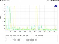
More images. Test set up. Modulation signals at 24, 48 & 96 Hz. RC 10,000 ohms,.33uF. One at a time. Difference this time equal signal levels. Note the IM is higher than the THD. This follows my expectation of modulation due to the nonlinear mixing.
Attachments


Last edited:
Signal generator through capacitor into 10K resistor. Inject through capacitor and output across resistor.
OK yes, any time you develop a voltage across the cap, you get distortion. So, for a coupling cap, you use a very large value so the lowest freq does not develop any voltage across it. Used only as a DC blocking function.
However, in cross-overs and in filters - active and passive - it is a serious issue... so only the lowest DA caps should be used in filter circuits for audio/listening.
THx-RNMarsh
I do, you do, but there are a lot of folks arguing you don't with perfect capacitors. This one is among the best for low DA. This was a bigger issue with electronic analog computers.
Last edited:
More images. Test set up. Modulation signals at 24, 48 & 96 Hz. RC 10,000 ohms,.33uF. One at a time. Difference this time equal signal levels. Note the IM is higher than the THD. This follows my expectation of modulation due to the nonlinear mixing.
It would be interesting if we could have a little more information:
What type of cap and voltage rating?
Test signal voltage?
What does it look like if cap replaced with a short? Perfect?
.33 uF polypropylene 1400 volt rating.
Test signal is shown 0 dB = 1 volt or 7 V RMS 20 Peak to Peak.
Just look at the noise floor on each pass that is where the dirt is, side bands are 10-20 dB above that. They also are at the levels that would be expected from the amount of exponential non-linearity for the capacitance and frequencies used. Generator harmonics wouldn't move. The 60 Hz infiltration stays the same.
Note that the IM distortion is well above the THD. It also drops very slightly at the octaves above and below the Xc = R center frequency. Capacitor deviations from perfect should show up as THD. EI curve modulation should be sidebands. Pretty much what I expected.
Tomorrow if I get the chance why and when non-linear components are useful. Maybe even same plot without a series capacitor and a much larger one.
Try search for Bruce Hofer slides of "Designing for Ultra-Low Distortion and Noise in Analog Circuits"
Oops, this is for sine waves, may be not necessary for audio.
Designing for Ultra-Low THD+N - Audio Precision
I do, you do, but there are a lot of folks arguing you don't with perfect capacitors. This one is among the best for low DA. This was a bigger issue with electronic analog computers.
It is still an issue. How does one make a filter for speaker cross-overs or for RIAA or bass cut-off, or EQ etc without voltage developed across a capacitor? yet, if you like to pretend again that caps are only used as coupling and just use a large enough value C... nill distortion and then conclude caps dont generate any or at least audible changes to signal and sound.....well...So what, I say. Coupling isnt the only use for caps in audio or anywhere else either. And, larger DA also gives larger changes to waveform and thus sounds different from a perfect or no C.
Decades ago, I measured mostly 2H with FFT of DA and this may be due to the biexponential curve (taking only the dominant first two C and DA R-C of Dow model).
THx-RNMarsh
Last edited:
...EI curve modulation...
Actually, there doesn't have to be EI curve modulation, well, depending on what you mean by that. That is to say, the curve doesn't have to be changing shape, it only has to be curved for intermodulation to occur. The same curvature that creates THD is fine.
Example would be a single diode passive RF mixer, although it could work at low frequencies too. The diode curve is fixed, but intermodulation results just because two frequencies are applied at once.
There can also be what could be termed nonlinear-nonlinearity where the curve shape is changing, in addition to two frequencies being applied at once. Say, maybe from heating and cooling during the operating cycle. Probably more conventional to describe something like that as nonstationary-nonlinearity (i.e. the nonlinearity is changing over time).
Take a look at the level of the first side band for each 24, 48 or 96 Hz lower frequency. I see that the 48 Hz one is a bit higher than the others. Could be a perception bias.
Now go back to my nonlinear resistor plots. One is done with a voltage induced thermal shift, very obvious pattern.
The EI curve may be changing, but I am just refering to an EI plot that is not a straight line. You seem to understand anything but a straight line produces IM.
The arguement Scott was trying to make is that there is only phase shift of a sine wave due to the TC network and the low frequency may be attenuated and phase shifted but the signals still algebraicly add. Mine is that higher voltages increase the current and decrease the charging time. So that when the two signals combine there will be changes in the low frequency charge rate that occur at the higher frequencies rate. So there should be some intermodulation.
There may be other issues. As capacitance is related to area/distance there must be some mechanical compression following the voltage. That is why high voltage capacitors have less distortion than almost identical lower voltage ones.
All this started from my suggested experiment of loading a coupling capacitor with a variable resistor and switching in and out a short across the capacitor. That will easily show when the corner frequency can be perceived.
- Status
- Not open for further replies.
- Home
- Member Areas
- The Lounge
- John Curl's Blowtorch preamplifier part II