Hi Richard,
The old ways did change for a brief time in the early 80's. Then everyone seems to have forgotten what was learned.
Hi ticknpop,
Actually, I have tried it several times as customers bring equipment to me to undo damage from hack modifiers. Many of these hacks work in real storefront situations and should know better.
When I upgrade equipment, first I make certain the components fit. That's #1. As long as you are using good parts it matters not what name is on them. Very often the industrial parts outperform "audiophile approved" parts anyway. Make no mistake, those parts are still expensive, but not nutsy priced like the approved parts are.
It's really cool that you are that close. We should get together at some point to see what each is doing.
Best, Chris
The AP 2722 can be switched to direct (DC) or ac (capacitor) coupled.
I measured an unused/new 10mfd/50vdc bi-polar (85C) with .5v drop across it at 20hz showed -95dB THD. Almost to CD quality. larger volt drop thd goes up proportionately.
A 1 mfd polar type -- without DC bias cannot handle much above an applied .5v rms. A 1mfd polar was 5% with 1 volt across it. Unbalanced circuit topologies could use polar with bias on it. But thd is not as good as bi-polar or back to back polars.
A polycarbonate was 25 dB better and could take higher voltage across it without much change in thd.
Using ultra low distortion generator, ShibaSoku 725D and QA401 FFT to floating (battery powered) portable computer.
But, a relatively new amplifier -- Marantz MM7025 uses 3 polar in unbal and 4 polar in bal input before the PA itself. And these are all on IP and OP of opamps. yes, Polar type. Not even bi-polar.
The old ways have not changed for the low to middle class receiver/amp market. :-(
THx-RNMarsh
As another poster mentioned, AKM has measured -116dB THD+N with the AK4497 evaluation board which has 10uF polar electrolytic caps in series with the outputs which are biased at AVCC/2 (2.5V).
The AP measurements in the PDF show relatively flat distortion until higher frequencies.
Some forum members have measured Nichicon Muse ES bipolars also and found basically nothing:
Nichicon Muse ES bipolar caps measured: <-120dB THD, <-140dB IMD
I also own an EMU1820m which has tons of really cheap off-brand polarized coupling caps yet measures extremely well.
How do we reconcile these?
Different measurement conditions applied to the cap and different caps. I said only with a voltage drop across the cap. Not at a freq/load which would drop nill amount across the cap. For coupling cap applications.... my test would be for the bass or low freq end. Some mfr use smaller values to roll -off response below 20-40Hz. Esp RIAA circuits. But, also there are varying levels of bipolar performance. It wasn't the worst one. I didnt try to measure the best one I could find. It was a nichicon VX(M).
The sound-card measuring instruments is not accurate below about -100-105dB re 1v. You may show harmonics well below that level but it usually isnt very accurate.
Using polar caps for coupling (NO dc bias voltage on it) is really bad though. With opamps they are only needed for dc blocking/protection.
But, the DA is the bigger issue with polar/bi-polar as it affects the transient waveform which is more audible (compared to no cap) than the very low thd levels being measured - in-band.
Ever larger coupling cap values to be sure there is no voltage drop across the cap -- larger and higher cost - and several of them in series per channel is not as good a solution as DC servo and direct coupled topology - no caps.
And, again, other cap applications such as filters/EQ etc, where voltage drops across the dielectric makes a larger difference requires more attention to details.
I suspect that we have entered a new generation of buyers and designers. They will need to be educated all over again.
THx-RNMarsh
Last edited:
I also own an EMU1820m which has tons of really cheap off-brand polarized coupling caps yet measures extremely well.
How do we reconcile these?
Same here, I posted at least one loop-through of a cheap card with a multi-tone nothing of note. I don't think any of the second tier external devices like the Scarlet 2i2 going for $125 or so measures worse than -106dB or so. They all use piles of "crap" caps, please explain.
Simon thank you for your effort!
Would you mind repeating your measurement with a resistor, say 4k7 or 10k, instead of the cap? That would be the impedance of the 0.33uF capacitor at 50-100Hz.
In another thread some people have discussed the importance of source impedance on amplifier distortion. Would be nice if you can rule this effect out.
Different measurement conditions applied to the cap and different caps. I said only with a voltage drop across the cap. Not at a freq/load which would drop nill amount across the cap. For coupling cap applications.... my test would be for the bass or low freq end. Some mfr use smaller values to roll -off response below 20-40Hz. Esp RIAA circuits. But, also there are varying levels of bipolar performance. It wasn't the worst one. I didnt try to measure the best one I could find. It was a nichicon VX(M).
The sound-card measuring instruments is not accurate below about -100-105dB re 1v. You may show harmonics well below that level but it usually isnt very accurate.
Using polar caps for coupling (no dc voltage on it) is really bad though. With opamps they are only needed for dc blocking/protection.
But, the DA is the bigger issue with polar/bi-polar as it affects the transient waveform which is more audible (compared to no cap) than the very low thd levels being measured - in-band.
Ever larger coupling cap values to be sure there is no voltage drop across the cap -- larger and higher cost - and several of them in series per channel is not as good a solution as DC servo and direct coupled topology - no cap.
And, again, other cap applications such as filters/EQ etc, where voltage drops across the dielectric makes a larger difference requires more attention to details.
I suspect that we have entered a new generation of buyers and designers. They will need to be educated all over again.
THx-RNMarsh
The AKM measurements have 2.5VDC across the cap and they have a THD vs frequency sweep which shows flat distortion in the low frequency area.
All of those measurements were done with AP analyzers, not sound cards (both AKM's and the ones done by Twest/Tomchr)
Last edited:
The difference is what i tried to show. That if the C value allows the freq voltage to drop 1/2 across the cap, distortion will rise. This is well established by several others, as well. I didnt do any biased polar measurements --- thats all been done long ago. But, from others work (WJ), a bias is needed for low distortion .... but apparently, not being done by some large corp. in their audio amplifiers.
Even in the QA400/401, they have dc blocking electrolytics in series with input but the C value and 10K Z is such that no voltage at any reasonable low freq would be developed across the C. So, distortion is low enough to not be seen by this analyzer. I have shorted those input caps and not seen an improvement with the FFT results. So the distortion is below -100 for sure.
In the AP analyzer, they use a much better and lower DA cap in series. A selected PP. AP also does a lot of other tests and so the highest quality cap is needed to accurately measure to levels lower than sound cards.
In my test setup, I only use the top 60dB of range (0 to -60dB) of the QA401 so i dont see any spurious contribution.... only what is there from the analyzer monitor port.
THx-RNMarsh
Last edited:
🙂
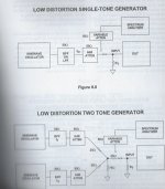
Well, Ummm, I don't have one of those AP devices. I assume it has two separate analog oscillators? If so, the question I would have is how are the oscillator outputs being combined to drive the test fixture with two frequencies at once? Maybe outputs connected together directly, maybe through an active combiner (low distortion amplifier?), or passive network combiner? Is it done internally to the AP?
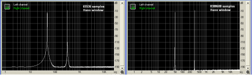
Generating a dual test tone in software gives good results.
Here is a two minutes long file 24bit/48kHz with two 1:1 sinusoids –6dBFS one at 48.340Hz, the other at 320.068Hz
Dropbox - DualTone48.340Hz-320.068Hz 1 to 1 at -6dB_24b-48kHz mono.wav
George
Attachments
Generating a dual test tone in software gives good results.
Here is a two minutes long file 24bit/48kHz with two 1:1 sinusoids –6dBFS one at 48.340Hz, the other at 320.068Hz
Dropbox - DualTone48.340Hz-320.068Hz 1 to 1 at -6dB_24b-48kHz mono.wav
George
🙂 😎
THx-RNM
Some more AP measurements showing that little or nothing is there.
Why are people obsessed with coupling caps? | SYclotron Audio
Why are people obsessed with coupling caps? Part 2 | SYclotron Audio
Why are people obsessed with coupling caps? | SYclotron Audio
Why are people obsessed with coupling caps? Part 2 | SYclotron Audio
Some more AP measurements showing that little or nothing is there.
Why are people obsessed with coupling caps? | SYclotron Audio
Why are people obsessed with coupling caps? Part 2 | SYclotron Audio
From the guy who didn't know C=q/V. Couldn't measure the difference between an electrolytic and a film capacitor. SY is trying to prove his point, not really doing a curiosity bit.
BTY one of my guys wants to test guitar cables and mark them for best use direction. Only problem is do guitarists want the highest or lowest distortion?
If you ever stop by I can let you play with the measurement gizmo yourself.
Part of posting here is the often well informed advice and critiscm. One of which is dismissing appeals to "experts."
And to add additional insult, don't you love it when someone trys to prove a negative
Last edited:
Of course, the cap(s) in a servo will be of much lower value, for the same bandwidth, but i wonder your words "No cap".several of them in series per channel is not as good a solution as DC servo and direct coupled topology - no caps.
The caps are in the signal path in a servo.

Only problem is do guitarists want the highest or lowest distortion?
Believe or not, guitar distortion needs to fit suitably into a song arrangement, just like any other instrument. It's not a simple more or less of it type of thing.
Of course, the cap(s) in a servo will be of much lower value, for the same bandwidth, but i wonder your words "No cap".
The caps are in the signal path in a servo.
No cap referring to no coupling caps.
Servo ---- Not always -- depends on implementation.
A good subject. How do you implement it so the servo does not affect sound?
THx-RNMarsh
Last edited:
Ed
Scott is biased as much as you on this, only he supports the benign, you the malicious nature of coupling caps.
Where do you think is the flaw in those measurements and/or the setup by Scott?
The load is lighter, at 100kOhm.
He even uses an AP 🙂
George
Scott is biased as much as you on this, only he supports the benign, you the malicious nature of coupling caps.
Where do you think is the flaw in those measurements and/or the setup by Scott?
The load is lighter, at 100kOhm.
He even uses an AP 🙂
George
Ed
Scott is biased as much as you on this,
I read Sy's articles and I would agree that Sy, and by implication from linking to Sy and his particular choice of words, apparently Scott, appear to be both strongly biased regarding the issues in question.
Also, Sy's position doesn't seem to be exactly the opposite of Marsh and Curl since their bias in this case seems to be against capacitors. On the other hand, Sy's bias in the two articles, seen partly in regard to capacitors and partly in the form of ridicule and contempt of others, appears to be significantly and disrespectfully directed towards persons he doesn't like and whom he considers beneath himself. I sure wish Scott had been able to locate a more neutral piece to express his point of view.
Last edited:
- Status
- Not open for further replies.
- Home
- Member Areas
- The Lounge
- John Curl's Blowtorch preamplifier part II