Scott
Can we agree a perfect capacitor follows C = q/V ?
It does not follow, it is defined that way. Nobody wants to retract the definition.
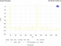
(leftmost plot in #99871)
But, it seems your AP outputs both +10 dBV signals, that would be +16 dBV for both together. At the same time you expect -125 dBV as the "no effect" level. Please, what output amplifier / ADC circuit should have that performance?
In my time at Verigy (ex Agilent) I had my "own" 93000 mixed signal wafer tester, and it also had an AP (quite a bitch to integrate, btw.) Nobody would have ever expected that dynamic range from it.
When you suggest that the capacitor is the culprit, why is there no measurement with a wire instead of the cap?
And why is the IMD3 at 60 Hz stronger than that at 290 Hz and the IMD5 falls steeper? For symmetry reasons that is not to be expected given the same nonlinearity.
Also, I miss somehow the lower sideband around the 20 Hz carrier. That should alias to abt. 40 Hz? (could be wrong, bed time overdue)
That the low frequency IMD is worse than the high freq. could mean that we see an angry AGC leveling loop, which is of course speculation.
Cheers, Gerhard.
Direct coupled Borbely jfet phono stage with all Relcap films - 1% teflon RIAA caps, polystyrene servos, teflon bias bypass, and Blackgate electrolytics. And glue to hold the oversize parts in place. Teflon pc board. 90 ma output stage bias.
Front end is 4 x 2SK147 and 4 x 2SJ72 jfets
Really, I cannot understand this Teflon fetish in audio circles. For frying pans it may be OK, nothing sticks to it, no eggs and no PCB traces. It may have a low loss tangent, but it has also a structure like a sponge. It sucks up gases, hydrocarbons, moisture and lets them go again on the right conditions. In space applications it is generally frowned upon, we usually had to apply conformal coating, so it kept the dirt for itself and did not gas out on the optics.
regards, Gerhard
+1Really, I cannot understand this Teflon fetish in audio circles.
There are lots of fantasies about this material. Probably because he was classified by the US army during seven years after his discovery.
Gerard,
Around here I have had folks disagree with the definition of capacitance which is why there is that question.
The 60 hertz spike is AC power line noise. The side bands are at 48 and 72 hertz.
But thank-you for correcting my signal level mistake. Will rerun at a lower level and do a plot without a capacitor. Did one before the set shown but that was at a lower level.
Thanks again for pointing out the obvious that I missed.
M4
We should agree on the difference between ideal and perfect. Ideal to me fits the application, perfect follows the definition. Should we discuss the difference between E & V?
Should we discuss the difference between E & V?
Usually, they are taken as units for EMF, the force associated with electric fields. E and V mean the same thing, volts.
Upper case letters are steady state, and lower case are instantaneous, unless otherwise specified. There are always exceptions, depending.
Is there something else you have in mind?
EDIT: Regarding perfect as opposed to ideal, there is no standard definition in the EE profession for perfect components that I can think of. Usually, it would be taken as a casual synonym for ideal.
Last edited:
I knew I would take beating for the teflon caps, I didn’t even get to the metal foil resistors or silver wire.
Hi ticknpop,
Whoever installed those capacitors should be taken out and shot! Capacitors of equal or better performance are available that will fit properly for one. They will not have popular names printed on them. You are risking signals being sent and received by those large antennas that you have there.
Try and take the schematic and draw in the strays. Now, can it be returned to factory trim, or did the holes get enlarged? I suspect the PCB holes needed to be enlarged.
The resistors and wire are just simply silly. Audio jewelry for you. I guess the equipment is intended to run with the cover off and turned so that the interior can be marvelled at. 😀
Honestly, you could get real performance gains using normal components, metal film resistors in some locations and normal wire.
-Chris
Anatech,
i live 20 minutes from you, it works (very well) as built. So does the line amp and power amp built the same way. No extraterrestial signals despite long leads. Don’t knock it until you try it.
i live 20 minutes from you, it works (very well) as built. So does the line amp and power amp built the same way. No extraterrestial signals despite long leads. Don’t knock it until you try it.
Last edited:
R.N.Marsh will thank-you for your Multicaps ;-)I knew I would take beating for the teflon caps, I didn’t even get to the metal foil resistors or silver wire.
http://www.partsconnexion.com/PDF/mcap2.pdf
M4, Gerhard,
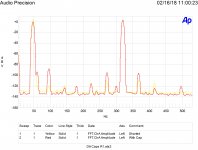
48 Hz with capacitor and shorted. Level dropped. 96 and 272 are interesting, 362 gets kind of lost.
More advice can be followed on Monday.
ES
Thanks for the re-run of the plots. The 60 Hz hump sadly doesn't inspire confidence, as it's by and large the biggest change from loopback to RC circuit, which doubly suggests that the loop area of your circuit has grown considerably to pick up the 60 Hz. At 1 ppm error rates, everything under the sun starts creeping into a seemingly innocuous experiment.
Thanks for the re-run of the plots. The 60 Hz hump sadly doesn't inspire confidence, as it's by and large the biggest change from loopback to RC circuit, which doubly suggests that the loop area of your circuit has grown considerably to pick up the 60 Hz.
The unshielded loop doubles when the capacitor is added. Exactly the opposite the 60 Hz. components show the measurements are real and consistent.
If can find it, the parts can be soldered into a full metal enclosure with BNC connectors.
🙂
Well, Ummm, I don't have one of those AP devices. I assume it has two separate analog oscillators? If so, the question I would have is how are the oscillator outputs being combined to drive the test fixture with two frequencies at once? Maybe outputs connected together directly, maybe through an active combiner (low distortion amplifier?), or passive network combiner? Is it done internally to the AP?
Other than that, my preliminary impression is that the capacitor is quite good if ever so slightly a departure from ideal. Maybe about as ideal as it gets under the conditions as measured.
M4, Gerhard,
48 Hz with capacitor and shorted. Level dropped. 96 and 272 are interesting, 362 gets kind of lost.
More advice can be followed on Monday.
ES
Well, Ummm, I don't have one of those AP devices. I assume it has two separate analog oscillators? If so, the question I would have is how are the oscillator outputs being combined to drive the test fixture with two frequencies at once? Maybe outputs connected together directly, maybe through an active combiner (low distortion amplifier?), or passive network combiner? Is it done internally to the AP?
Other than that, my preliminary impression is that the capacitor is quite good if ever so slightly a departure from ideal. Maybe about as ideal as it gets under the conditions as measured.
Last edited:
🙂
Well, Ummm, I don't have one of those AP devices. I assume it has two separate analog oscillators? If so, the question I would have is how are the oscillator outputs being combined to drive the test fixture with two frequencies at once? Maybe outputs connected together directly, maybe through an active combiner (low distortion amplifier?), or passive network combiner? Is it done internally to the AP?
Other than that, my preliminary impression is that the capacitor is quite good if ever so slightly a departure from ideal. Maybe about as ideal as it gets under the conditions as measured.
I would expect D/A and one amplifier. The inherent distortion didn't seem to change with level.
As to the capacitor I expect it is one of the best. Of course I haven't tried Teflon....
The unshielded loop doubles when the capacitor is added. Exactly the opposite the 60 Hz. components show the measurements are real and consistent.
If can find it, the parts can be soldered into a full metal enclosure with BNC connectors.
Enclosure would be good. For the record, I don't doubt you are measuring what you're measuring. I'm just quite incredulous you're measuring nonlinearities in capacitors, versus carefully measuring something different. 🙂 So having a 20+ dB spike in 60 Hz show up and 10 dB change in IM products, all sitting extremely close to the floor sensitivity of the system, gives me pause.
Enclosure would be good. For the record, I don't doubt you are measuring what you're measuring. I'm just quite incredulous you're measuring nonlinearities in capacitors, versus carefully measuring something different. 🙂 So having a 20+ dB spike in 60 Hz show up and 10 dB change in IM products, all sitting extremely close to the floor sensitivity of the system, gives me pause.
Not as good capacitors show up much better. But who would use them? Oh wait there are folks who prefer carbon composition resistors...
I also expect the results to vary with humidity and exposure time.
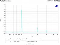
If you want to measure capacitor distortion the 4/1 and 1/4 bridge technique shows it easily.
First image is a bad capacitor in the current setup. The second is a mylar in the bridge set up. Note the fundamental is nulled a bit from the 0 level.
Attachments
I would expect D/A and one amplifier. The inherent distortion didn't seem to change with level.
As to the capacitor I expect it is one of the best. Of course I haven't tried Teflon....
Hmmm. I seem to be saying that a lot recently. 🙂
It sounds like signal generation is entirely internal to the AP, with only one output connector going to the test fixture?
I'm wondering why there is as much IMD as there is with a short in place of the capacitor (but, the line frequency noise is understandable), Either the IMD is internal to the instrument, or to the remaining parts of the test fixture. Nothing else left, is there?
A few questions occur to me along the lines of these:
Is it known what's the normal residual distortion for two tone IMD measurement for the AP model you have? Can you plug the oscillator output right back into the analyzer input and bypass the test fixture? Is there an internal loopback mode to check for normal operation?
Last edited:
When I get a chance I can jump out to in. There are two outputs but on the dual setting they both are the same. Gerhard was right about it being the AP, but output level doesn't seem to have much effect. I expect -130 resolution doing an FFT and at least -120 on a sine output. Have to check to see what it is doing these days.
Yes Daniel, experiment measurements should be clean first to be considered reliable and trustworthy.
The AP 2722 can be switched to direct (DC) or ac (capacitor) coupled.
I measured a single unused/new 10mfd/50vdc bi-polar (85C) with .5v drop across it at 20hz showed -95dB THD. Almost to CD quality. With a larger volt drop, the thd goes up proportionately.
A 1 mfd polar type -- without DC bias cannot handle much above an applied .5v rms. A 1mfd polar was 5% with 1 volt across it. Unbalanced non-push pull with 1/2 Vs on output circuit topologies could use polar with bias on it. But thd is not as good as bi-polar or back to back polars.
A polycarbonate was 25 dB better and could take higher voltage across it without much change in thd.
Using ultra low distortion generator, ShibaSoku 725D and QA401 FFT to floating (battery powered) portable computer.
But, a relatively new amplifier -- Marantz MM7025 uses 3 polar in unbal and 4 polar in bal input in series before the PA itself. And these are all on IP and OP of opamps. yes, Polar type. Not even bi-polar. Plus one polar in PA gain to ground fb.
The old ways have not changed for the low to middle class receiver/amp market. :-(
THx-RNMarsh
Last edited:
- Status
- Not open for further replies.
- Home
- Member Areas
- The Lounge
- John Curl's Blowtorch preamplifier part II