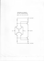
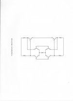
A couple of reminders. These are basic subcircuits that are used by Parasound, for example for amps and preamps. There are more sophisticated topologies, but they are harder to make, and are not used by Parasound for this reason.
Attachments
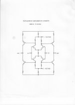
I would next talk about the second stage connections to the complementary differential and its relative advantages over a single differential pair. As can be seen, the second stage has true push-pull in its second stage driver stage, whether it is single complementary or differential complementary. This is more linear, all else being equal than any single drive (with an active load, bootstrap, or resistor) or single differential with a current mirror, resistor, or active load(s). This is the second major advantage of the complementary differential input stage.
Last edited:
Another advantage to the complementary differential input stage is that the slew rate will be symmetrical, due to the fact that the comp caps (wherever they are) are equally driven with a push pull drive.
John,
I've always been intrigued by the drive to the second-stage devices in your complementary differential topology. In your circuit, you differentially drive both the bases and the emitters of the second-stage devices, a configuration which I've observed tends to take the transfer characteristics of the second-stage devices out of the circuit from a sonic contribution standpoint (yielding a more sonically neutral sound to the circuit). This is different from most complementary differential topologies that I've seen, which usually just drive the second-stage device bases or feed the input-stage output signal into the emitters of the second-stage devices (which effectively converts the circuit into a folded cascode).
Could we get you to expound on the benefits of this elegant topology? Also, since it's your design, have you ever assigned a name to the circuit (as in a Curl "curl")? I've read that Grey Rollins asked you for a circuit name several years ago.
Thanks for your input EL34, but I refrain from using my name on circuits. We will discuss the folded cascode next, if I can make any headway.
Last edited:
A couple of reminders. These are basic subcircuits that are used by Parasound, for example for amps and preamps. There are more sophisticated topologies, but they are harder to make, and are not used by Parasound for this reason.
essentially the resistors can be considered theoretical, and the source of distortions becomes one of symmetry in layout/execution, symmetry and perfection in power supply, and most essentially, device matching.
When it comes to the devices themselves, it appears that the overall complex characteristics of the devices themselves will be the limiting factor in any distortions of high delta signal and it's handling. The error of the one (device) will accumulate into existence along with the error of the other (mirror). Inequities in the given mirror become the appearance of being the sole distortion component, if properly implemented.
The rest (distortions) will creep into existence (power supply, mechanistic symmetry issues, etc), as theory is not reality, no matter how much we may desire it to be.
Basically the circuit will be very neutral, nearing perfection, until high deltas enter the equation and raise the issue of micro differentials between the devices.
Basically the circuit will be very neutral, nearing perfection, until high deltas enter the equation and raise the issue of micro differentials between the devices.
To the contrary , this topology is the best one
large signal mode wise...
I stated something that is... rather obvious, I hope, but maybe what I was saying was not interpreted the way I meant it, so I'll do as John has suggested. '-)
It's all about the tunes, so I don't mind:
http://www.youtube.com/watch?v=vYSx31MlX5M
It's all about the tunes, so I don't mind:
http://www.youtube.com/watch?v=vYSx31MlX5M
Last edited:
Best comp cap is none. Or a tiny bit of copper on FR406😉.
I fail to see how copper wires between my phono cartridge and loudspeakers will produce audible music.
Yes, Wavebourn, many medium power transistors work well enough for low noise inputs. I used the Fairchild 8050 and 8550 two amp complementary output transistors in the late 70's in the Sota MC Head Amp, and got 0.4nV/rt Hz.
Here's another one - MJE13007, they're quoting < 0.4nV/rt Hz
Extreme Low Noise Preampifier
Has anyone measured 2SC3298 or equiv?
Zetex in their Design Note 11, Issue 2 June 1995, describes the use of ZTX650 or ZTX690B series devices for NPNs, and ZTX750/ZTX790A series for PNP, and cite "typically a few ohms" for the base spreading resistances. These are 1W free-air dissipation devices and have o.k. beta (for example, at 50mA the ZTX750 is given as typically 200) and the capacitances aren't gigantic ( Cobo 30pF at 10V for the 750). F sub t is an o.k. 140MHz at 500mA/5V. No curves of beta or F sub t are given, so beta flatness is difficult to judge other than from a few table entries, most of which are for high currents that would not likely be optimal for even rather low source impedances.
BTW Beis in his piece is a bit confused about the noise at the emitter(s) for the INA103. It's not higher than the base current noise, but the magnitude of the standing current is of course much higher, so it does require a very low impedance to bias properly and generate less noise than that to which the device e sub n limits us. This is a general result for noise in active devices (see Motchenbacher and others for a discussion). Practically speaking the situation gets absurd for very high impedance sources used with JFETs, because there is no way to bias a common-gate stage with anything approaching the required low noise of the device itself.
I've not used the Zetex devices.
Brad
I've not used the Zetex devices.
Me too. I have some ZTX650, but several years don't dare to waste them.
I'm advised privately that numbers and packages have changed for the parts since the acquisition by Diodes Inc., and at least the 650/750 devices are now renamed and in SOT223 packages.


- Status
- Not open for further replies.
- Home
- Member Areas
- The Lounge
- John Curl's Blowtorch preamplifier part II