Hello Again,
I have been searching through my documentation and have found a third construction manual! This one is 19 pages and is entitled K1100 Series Power Amplifiers - Version 2. I suspect this is a later version still. Again, I am happy to scan it, if you let me know.
Best wishes
I have been searching through my documentation and have found a third construction manual! This one is 19 pages and is entitled K1100 Series Power Amplifiers - Version 2. I suspect this is a later version still. Again, I am happy to scan it, if you let me know.
Best wishes
Hello David
yes that's the one, but there is only one page in the pdf file ?
yes please if you could scan it for me I would be very grateful
best regards
yes that's the one, but there is only one page in the pdf file ?
yes please if you could scan it for me I would be very grateful
best regards
Hello members
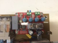
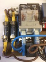
Have just made a little soft start module for the 500va transformer that I am using for this project
It has mains in (top right corner terminal)
then terminal for the main on/off switch and out put to fans and protection modules and from the red circuit board goes to the primary transformer winding
hope this makes sense
Attachments
Also Please note :
the power supply PCB has a very small over site that is easily rectified (yes I have not the time to re visit the Gerber file)
this PCB 1150-3 has been modified to take the latest power supply capacitors and a small copper wire / track was left off . This is very simply added at the assembly stage by taking the cathode wire from D11to the base (centre) connection of Q14
That softstart PCB looks neat and tidy. I'm planning to add a solution with a high current NTC and relay with fixed RC time constant to shunt out the NTC (the same topology used in many high power SMPS).

@jamesfeline
Please find attached the latest construction maunual I have. I believe it relates to the same version of boards that you are using. Unfortunately, the circuit diagrams are not very clear as Hart used scanned copies from the original magazine articles. Hope this helps?
BTW - Your thread reignited my interest in this amp to the extent that I got it out, checked it over and had a listen. It's 30 years old, still works and sounds good! I also have a pair of bare Hart power amp boards so am considering building it again as I feel I could probably make a better job of it now! 🤔 🙂
Best wishes
David
Attachments
@DavidK I like this manual for its sense of practical work and humour. Espescially amplifier section's point 6 and power supply section's "expensive fireworks" term. 🙂
@didyman
Yes, the Hart manual is practical and straightforward. I am no expert but managed to successfully build the amp using it. Good luck with your build!
@jamesfeline
You are welcome!
Yes, the Hart manual is practical and straightforward. I am no expert but managed to successfully build the amp using it. Good luck with your build!
@jamesfeline
You are welcome!
Time for BOM. 🙂 I have all ideas about almost all components, but what about resistors? Metal-evaporated ones I think we prefer, even in power resistors. Dale, or other brand? Also have to find an idea about polycarbonate capacitors. I have never used them, wich brand is preferred? And, for Gate stoppers, I will not use SMD because of heat related mechanical problems. I plan to use through hole ones with dedicated low inductance types, but open for discussion.
Hello didyman
Don't worry about high quality stuff ... use what your budget allows
I have made these amps with budget components (not fakes) and it still sounds wonderful
Just use what you can afford budget wise .. but make sure all components are genuine
Don't worry about high quality stuff ... use what your budget allows
I have made these amps with budget components (not fakes) and it still sounds wonderful
Just use what you can afford budget wise .. but make sure all components are genuine
- Home
- Amplifiers
- Solid State
- JLH Mosfet Power amplifier construction thread