"search" posts by bob cordell and insert jFET buffer balanced as the search string.
It will take you straight to post in a list of just 3 answers
http://www.diyaudio.com/forums/soli...-complementary-input-stage-4.html#post1305166
It will take you straight to post in a list of just 3 answers
http://www.diyaudio.com/forums/soli...-complementary-input-stage-4.html#post1305166
"search" posts by bob cordell and insert jFET buffer balanced as the search string.
It will take you straight to post in a list of just 3 answers
http://www.diyaudio.com/forums/soli...-complementary-input-stage-4.html#post1305166
Andrew
Many thanks for your kind help.
Martin
Hi Dado,
I made the mod that you suggested for the mid point connection to earth. This didn’t solved my ground loop problem BUT improved the sound a lot : much more opened, transparent and razor-sharp image.
Thanks Dado!
I modified the Power Supply like this:
I made the mod that you suggested for the mid point connection to earth. This didn’t solved my ground loop problem BUT improved the sound a lot : much more opened, transparent and razor-sharp image.
Thanks Dado!
I modified the Power Supply like this:
Attachments
Hi Dado,
I made the mod that you suggested for the mid point connection to earth. This didn’t solved my ground loop problem BUT improved the sound a lot : much more opened, transparent and razor-sharp image.
Thanks Dado!
I modified the Power Supply like this:
I am glade you did some improvement. I am not familiar with Hart PCB, maybe there some more ground loop problems, don't give up.
dado
Hi all, Dadod
Now I suppressed the 15V supply for the bargraphs because of its earth connection. It gives further sound improvement. Very good mod too.
Some months ago I removed the balance circuit as I didn't need it: there was some improvement.
-> Can I then remove R8 and C7 (10uF) ?
Nicola
Now I suppressed the 15V supply for the bargraphs because of its earth connection. It gives further sound improvement. Very good mod too.
Some months ago I removed the balance circuit as I didn't need it: there was some improvement.
-> Can I then remove R8 and C7 (10uF) ?
Nicola
Hi all, Dadod
-> Can I then remove R8 and C7 (10uF) ?
Nicola
Is it a question now?
dado
Hi all, Dadod
Now I suppressed the 15V supply for the bargraphs because of its earth connection. It gives further sound improvement. Very good mod too.
Some months ago I removed the balance circuit as I didn't need it: there was some improvement.
-> Can I then remove R8 and C7 (10uF) ?
Nicola
NO, NO, this is a part of negative feedback. You can short R9 and remove balance pot if you like.
I never used that part. To keep the close loop gain you have to increment R8 by half R9 velue.
dado
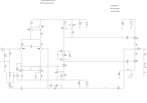
This one (schema of 1989):
There s a mistake in the schematic picture.
Q15 has its drain and source inverted.
A sensitivity of this amp is quite high (100mV for full output) and it was to much for me.
As you can see in my modification, described some pages back, I changed some things, between them open loop gain.
You canc calculate it as R14/R8+1 (if R9 is shorten), and in dB it is 20log(R8/R9+1).
dado
As you can see in my modification, described some pages back, I changed some things, between them open loop gain.
You canc calculate it as R14/R8+1 (if R9 is shorten), and in dB it is 20log(R8/R9+1).
dado
There s a mistake in the schematic picture.
Q15 has its drain and source inverted.
And Q12 but PCB is correct.
Hi Dado,
For your information, Hart removed R9 from 1992, put 10K balance pot (instead of 1K) and altered R8 to 1K5.
Question : should I put really R8 to about 2K (820+1100) with no balance circuit (R9 shorted and no balance pot) ?
Other question : did you had some problem with high frequencies before your mods ? I have some but I’m not sure from where they come from.
Nicola
You can short R9 and remove balance pot if you like.
I never used that part. To keep the close loop gain you have to increment R8 by half R9 velue.
For your information, Hart removed R9 from 1992, put 10K balance pot (instead of 1K) and altered R8 to 1K5.
Question : should I put really R8 to about 2K (820+1100) with no balance circuit (R9 shorted and no balance pot) ?
Other question : did you had some problem with high frequencies before your mods ? I have some but I’m not sure from where they come from.
Nicola
Last edited:
Hi Dado,
For your information, Hart removed R9 from 1992, put 10K balance pot (instead of 1K) and altered R8 to 1K5.
Question : should I put really R8 to about 2K (820+1100) with no balance circuit (R9 shorted and no balance pot) ?
Other question : did you had some problem with high frequencies before your mods ? I have some but I’m not sure from where they come from.
Nicola
If you put R8 to 2K you will get the same gain as if the balance pot was in the middle, that is valid for original JLH amp. I don't see how Hart changes coud functon??? Just removing R9 and changing a valus without changing circuit connection is no good. Be careful with changing Hart amp, must be different then JLH original schematic.
I have had some small high frequence oscilations with no load, and this was, in part, reason for my modifications. Other was to low OLG at 20kHz.
dado
Half the balance control is in parallel with 2k2 in the lower leg of the feedback.
If the balance control is to be removed then 50%*1kvr // 2k2 must be replaced with 407r for R9.
R9 & R8 can be summed and replaced with a fixed single resistor of 1227r for exactly the same gain. 1200r is close enough.
The reason JLH chose very high values of 150k for both R1 & r14 was to suit the low level outputs from contemporary sources of the previous decade.
This then complemented the use of a highish value for R*+R' to give some bass response with the film caps adopted in the NFB DC blocking position (4u7//4u7F = 9u4F)
Using 100k for R1 & R14 would suit most sources.
Using 2k7 or 3k for R8+R9' reduces closed loop gain to ~30 times. But this has two consequences:
1.) the bass response is extended slightly. 30ms cf. 11.5ms previously.
2.) the feedback is increased by a factor of [150k/1220] / [100k/3k] ~ 4times (+12dB). This will require some adjustments to the HF compensation to maintain JLH's standards of stability.
Last edited:
Half the balance control is in parallel with 2k2 in the lower leg of the feedback.
If the balance control is to be removed then 50%*1kvr // 2k2 must be replaced with 407r for R9.
R9 & R8 can be summed and replaced with a fixed single resistor of 1227r for exactly the same gain. 1200r is close enough.
The reason JLH chose very high values of 150k for both R1 & r14 was to suit the low level outputs from contemporary sources of the previous decade.
This then complemented the use of a highish value for R*+R' to give some bass response with the film caps adopted in the NFB DC blocking position (4u7//4u7F = 9u4F)
Using 100k for R1 & R14 would suit most sources.
Using 2k7 or 3k for R8+R9' reduces closed loop gain to ~30 times. But this has two consequences:
1.) the bass response is extended slightly. 30ms cf. 11.5ms previously.
2.) the feedback is increased by a factor of [150k/1220] / [100k/3k] ~ 4times (+12dB). This will require some adjustments to the HF compensation to maintain JLH's standards of stability.
This is my version I am using. Look at #47 too. Protection diodes are missing on the schematic, it was not relevant for the simulation.
dado
Attachments
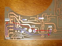
I've got the complete article and construction notes of the Original Hart Kit if anyone wants them. I built one of these.
It's still working but showing its age now - almost 20 years on.
It's still working but showing its age now - almost 20 years on.
So I’ll try first this config :
R1=100K, R14=100K, R8=1200R, R9=removed, RV3 preset=removed, balance pot=removed.
Note : R9 doesn’t exist on my Hart PCB.
Question : is this config OK ?
I’ll report when done.
Thanks to both Dado and Andrew for your comments and explanations.
Output level of my sources are 2V and 100mV, and I use B1 buffer preamp.
Nicola
So I’ll try first this config :
R1=100K, R14=100K, R8=1200R, R9=removed, RV3 preset=removed, balance pot=removed.
Note : R9 doesn’t exist on my Hart PCB.
Question : is this config OK ?
I’ll report when done.
Thanks to both Dado and Andrew for your comments and explanations.
Output level of my sources are 2V and 100mV, and I use B1 buffer preamp.
Nicola
Nikola,
I think it should be OK. Instead of 42dB as for original Hart you will get 38dB of the gain.
dado
- Home
- Amplifiers
- Solid State
- JLH 80w mosfet power amplifier - modifying it