Hi
Will using Carbon variable Resistors instead of Cermet make a difference to the sound quality, I have had no luck finding the same pattern cermet variable resistors as used by Hart. These are the last items I have to find then I can start construction.
Will using Carbon variable Resistors instead of Cermet make a difference to the sound quality, I have had no luck finding the same pattern cermet variable resistors as used by Hart. These are the last items I have to find then I can start construction.
Hi
Will using Carbon variable Resistors instead of Cermet make a difference to the sound quality, I have had no luck finding the same pattern cermet variable resistors as used by Hart. These are the last items I have to find then I can start construction.
Hi
I meant to say the preset cermet resistors = Power Supply RV1, RV2 - 10K and RV3, Rv4 - 22K and the Power Amplifier RV 2 and RV4 - 1K and RV5 - 2K2. I have not been able to find any trim-pots with the same pin spacing as per the Hart PCB's. Probably I will have to use vareoboard and spills to use the 5mm pin spacing of more modern pots. But I was trying to keep it as neat as possible.
Many thanks
martin
I don't see the problem using carbon pot, only reliability if it is an open type.
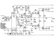
HI Everybody. I am new to this way of finding stuff, so please excuse the mistakes. A friend is busy assembling a JLH 80 -100 Watt MOS FET amp I started in 1984 and never finished. It came from the May to October editions of ETI. Now I cannot find my August edition and is stuck. Can anyone please help with this article.
Hi all,
Finally I realized the Dado’s mod described in post #47.
It is very rare to find practical mod articles on this JLH 80W, although I consider this amplifier very good despite its age. This thread produced interesting suggestions and Dado’s mod was apparently a good opportunity to push JLH 80W beyond the limits. The distorsion improvement figures found by him were impressive enough to try the move, but apparently nobody else made the change or wrote about it.
My source is standard Teac VRDS-25 with unmodified Benchmark DAC-1 and my loudpeakers are recabled monitors Spendor 2/3E : the system is very transparent and revealing.
In my setup : R1 & R14 are 100K, and R8 is 2K2.
C3 is 330p now,
R3 is 100R,
C4 is deleted,
C5 is 47n,
R10 is 100R,
C8 (5p) is not changed for my setup (10p in Dado’s mod).
I’ve cut one track twice at R10 pad to keep it alone and I’ve added two (isolated) links on my Hart PCB (1989 schema) :
Remember that schema and PCB are two different things ! I learned that the hard way... So check carefully before!
It is not easy to describe differences because the sound changes a lot from one recording to the other, or with different sources.
The sound is cleaner, more readable, less spectacular because some resonances disappeared through the spectrum and distortion reduced, but more refined, quieter, more natural, more pleasant and easier to listen to. Treble is very clear now. The listening style changed and improved with a significant margin : it was necessary to accustom a bit because of the reduced distortion.
The improvement is obvious. Just allow several hours after the mod to open the image up.
I find the Dado’s mod icing on the cake in my setup. It is well worth the effort and I’ll keep it definitively !
Thumbs up, Dado !
Nicola
Finally I realized the Dado’s mod described in post #47.
It is very rare to find practical mod articles on this JLH 80W, although I consider this amplifier very good despite its age. This thread produced interesting suggestions and Dado’s mod was apparently a good opportunity to push JLH 80W beyond the limits. The distorsion improvement figures found by him were impressive enough to try the move, but apparently nobody else made the change or wrote about it.
My source is standard Teac VRDS-25 with unmodified Benchmark DAC-1 and my loudpeakers are recabled monitors Spendor 2/3E : the system is very transparent and revealing.
In my setup : R1 & R14 are 100K, and R8 is 2K2.
C3 is 330p now,
R3 is 100R,
C4 is deleted,
C5 is 47n,
R10 is 100R,
C8 (5p) is not changed for my setup (10p in Dado’s mod).
I’ve cut one track twice at R10 pad to keep it alone and I’ve added two (isolated) links on my Hart PCB (1989 schema) :
- Track cut from R10 to D1,R18,R19,C13...
- Track cut from R10 to Q8,Q9 -> this R10's pad is alone now.
- Two isolated links added: one from same R10 pad to track going to Q8,Q9 ; the other from same R10 pad to R25,R23,D3...
Remember that schema and PCB are two different things ! I learned that the hard way... So check carefully before!
It is not easy to describe differences because the sound changes a lot from one recording to the other, or with different sources.
The sound is cleaner, more readable, less spectacular because some resonances disappeared through the spectrum and distortion reduced, but more refined, quieter, more natural, more pleasant and easier to listen to. Treble is very clear now. The listening style changed and improved with a significant margin : it was necessary to accustom a bit because of the reduced distortion.
The improvement is obvious. Just allow several hours after the mod to open the image up.
I find the Dado’s mod icing on the cake in my setup. It is well worth the effort and I’ll keep it definitively !
Thumbs up, Dado !
Nicola
Hi Nicola
Many thanks for details of your MOD, I have prepared a PCB using your's and DADO power supply board earthing mod and am slowley getting it soldered up.
Many thanks for details of your MOD, I have prepared a PCB using your's and DADO power supply board earthing mod and am slowley getting it soldered up.
Moving R10 from VAS to output changes the amplifier.
It is no longer a JLH.
It becomes very conventional. Everyone except the Brits do it the simple way.
Maybe the "Brit" sound does not suit you.
It is no longer a JLH.
It becomes very conventional. Everyone except the Brits do it the simple way.
Maybe the "Brit" sound does not suit you.
Hi Andrew,
Technically I don’t know.
About the sound : my words about change in style were probably not well chosen. Now the sound is in the straight line as before, but I should to accustomate to much less distorsion that it appears as a new « style » but it is not. This was obvious when I compared instantly modified channel with the unmodified one for several hours before going to full modification.
The scene is still colourful and colours are enhanced. If british sound is distorsion, then perhaps I don’t like british sound... To be sure that I understand you, could you explain what is british sound ?
Nicola
Many British Power Amplifier designers do not use the Cdom (as used by D.SelF) method of stabilising the amp.
Instead they capacitor couple the VAS to the inverting input.
This generally requires a much more thorough and usually multi-location method of ensuring amp stability.
This style of topology was relatively uncommon outside the UK while it was being adopted inside a number of British, nice sounding, amplifiers during the 70s, 80s and 90s.
There are some non British amp designers who champion this style of compensation, either exclusively, or in conjunction with low values of Cdom.
Many British Power Amplifier designers do not use the Cdom (as used by D.SelF) method of stabilising the amp.
Instead they capacitor couple the VAS to the inverting input.
This generally requires a much more thorough and usually multi-location method of ensuring amp stability.
This style of topology was relatively uncommon outside the UK while it was being adopted inside a number of British, nice sounding, amplifiers during the 70s, 80s and 90s.
There are some non British amp designers who champion this style of compensation, either exclusively, or in conjunction with low values of Cdom.
Original JLH value for R10 is 470kohm and this is not just capacitor coupled from the VAS to the inverting input. If this could be reason for so called "British sound" I don't know and by the way what is the British sound, some specific kind of distortion.
The main reason I started with modification of JLH amp was that I have a hum coming from loudspeaker. I have found that the wrong earthing in JLH design was the case.
Then I started to look with an oscilloscope and found small oscilation with no load connected. In time when I have built the JLH amp I did not have an oscilloscope so I have just built it and It worked for years with described problems.
I simulated it and dasided to modify it according the simulation result, and I like the sound more now. Finally I still think this remains the JLH 80W amp as the main design goals are not changed.
dado
Bargraph Suppression
Hi Nicola
Can you please explain how you suppressed the 15 volt Bargraph supply and what values you used.
I have just got back to the JLH rebuild having spent the summer rebuilding my old turntable.
Many thanks
Martin
Hi all, Dadod
Now I suppressed the 15V supply for the bargraphs because of its earth connection. It gives further sound improvement. Very good mod too.
Some months ago I removed the balance circuit as I didn't need it: there was some improvement.
-> Can I then remove R8 and C7 (10uF) ?
Nicola
Hi Nicola
Can you please explain how you suppressed the 15 volt Bargraph supply and what values you used.
I have just got back to the JLH rebuild having spent the summer rebuilding my old turntable.
Many thanks
Martin
Hi Martin,
I suppose you’re using the PSU PCB from Hart.
The zone to look at is well delimited.
Suppress the following components :
R44, R45, R47, R48, R49, R50;
C13, C14;
D34, D35;
Q23, Q24;
the 3 links that are placed between C11 & C12.
After this mod, there is only three components left in the zone : the link next to C14 and, of course, C11 & C12!
Nicola
Last edited:
Thanks for the reply yes I am using the Hart PCB 1150-3. I am rather a novice at electronics I can build a kit and follow a circuit diagram but theory is my failing. I have identified the placement of the components that you mentioned but I do not understand how to suppress them. Sorry to be so dumb. Did you build your JLH from a Hart Kit?Hi Martin,
I suppose you’re using the PSU PCB from Hart.
The zone to look at is well delimited.
Suppress the following components :
R44, R45, R47, R48, R49, R50;
C13, C14;
D34, D35;
Q23, Q24;
the 3 links that are placed between C11 & C12.
After this mod, there is only three components left in the zone : the link next to C14 and, of course, C11 & C12!
Nicola
Hi Martin,
No problem. I'm learning too.
If you are unsure, then ask before!
Yes, I've the Hart kit.
Two options:
a) If you have already soldered the (listed) components on the board, then desolder them (=put them away).
b) If you have NOT soldered them yet, then don't solder them (=do nothing)
Nicola
No problem. I'm learning too.
If you are unsure, then ask before!
Yes, I've the Hart kit.
Two options:
a) If you have already soldered the (listed) components on the board, then desolder them (=put them away).
b) If you have NOT soldered them yet, then don't solder them (=do nothing)
Nicola
Hi Martin,
No problem. I'm learning too.
If you are unsure, then ask before!
Yes, I've the Hart kit.
Two options:
a) If you have already soldered the (listed) components on the board, then desolder them (=put them away).
b) If you have NOT soldered them yet, then don't solder them (=do nothing)
Nicola
Right I have got it, disable the Display. I had a stroke 3 years ago and the thought processes get a little muddled at times.
Did your Kit have the HITACHI Mosfets or the later EXICON ones, as I stated in an earlier post I built my JLH in the late 1990,s but My soldering was rather like the work of a village blacksmith so as I managed to get a set of PCB,s bfore Hart stopped trading I decided to do a complete rebuild.
I have decided to use the earthing mod that you posted and will go through the detailed post,s from DADOD to see if I can implement his mod.
Many thanks for your time
Martin
I have only come across this thread today To answer some of the questions raised
the vn1210m was manufactured by siliconix vn1210d was manufactured by supertex with the same die
so the only change is the power disapation The data sheets are available at alldatasheet.com the package is to-237 I have some vn1720m devices if anyone would like some same die but 170vds
richie
the vn1210m was manufactured by siliconix vn1210d was manufactured by supertex with the same die
so the only change is the power disapation The data sheets are available at alldatasheet.com the package is to-237 I have some vn1720m devices if anyone would like some same die but 170vds
richie
PCB etch Diags for JLH 80W amps ( hart )
Hi everyone - back in the day I built an integrated amp kit and then two mono blocks for my friend as he was single and could afford it!
Years have gone by, my kids are older now and I have somehow managed to misplace the old beast.
I would love to re-build, mono blocks - I may even bi-amp my TDL RTL3's with all the latest updates but I wonder if anyone has got any PCB diagrams for me to make them as I believe that they are not available anymore.
The Power supply I had was integrated toroidal onto the power supply board - if I do find the amp I may have to strip out all the components to duplicate the boards...but would be so much easier to have some transparencies made...
Has anyone got PCB plans at all please?
Thanks Tim
- Home
- Amplifiers
- Solid State
- JLH 80w mosfet power amplifier - modifying it