Connect midle of the transformer winding to the zero point of the large power supply capacitors and then from that point connect separate wire to the common chassis earth. Large current between winding and the capacitors should not go trough common earth point.
dado
Do you mean this ? my schema is according to the Hart power supply pcb.
Attachments

Not exactly, red wire to the +- of zero capacitors potencial and then with one wire to the earth. It looks that Hart connected earthing as JLH recomended and tha was wrong.

Last edited:
if yel & blu sec go to ~~, then red & gry must be centre tap.
Centre tap must go direct to the Zero Volts between the smoothing caps. This link is missing and instead you have shown long leads going to chassis.
Keep the transformer sec to rectifier to smoothing caps links short and twist all pairs together that have equal and opposing current flow.
Either Centre Tap or Zero Volts can be connected to Chassis.
This connection can have an optional disconnecting Network.
Chassis must be connected to PE permanently !
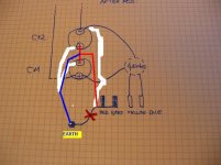
Keep the red wiring as short as possible. And Keep Loop Areas very small. This requires the four secondary wires from the transformer to be twisted together and only separate two to connect to ~ & ~. Then the two centre tap wires and the +ve & -ve wires are twisted as a group of four to go to the smoothing caps. Then separate the +ve & -ve to feed the smoothing caps.
Take a tapping off the blue line and run that to your Main Audio (Star) Ground. This Zero Volts tapping can be very close to the red but not actually on the red.
Take a tapping off the blue line and run that to your Main Audio (Star) Ground. This Zero Volts tapping can be very close to the red but not actually on the red.
Last edited:
Thanks, dado, for your improved schema ! I’ll try that.
Then the project would be my new photo (the blue lines are now real PCB tracks) :
I’m trying to use existing tracks if possible.
L1 is straight on from center tap to P1 to keep as short as possible (not shown so).
Is it OK to put potential zero for smoothing capacitors at P1 instead of P0 ?
Thanks, Andrew, for your information.
The two left blue lines on the left are designed on the PCB like this : two ‘long’ quite parallel lines going to common earth. Not as a single line. It would have been perhaps more logical for the PCB designer to link directly the + and – for potential zero of capacitors (separated only by a few centimeters) to have a single line going to ground. Could had been any reason for doing two paths to ground instead of one ?This link is missing and instead you have shown long leads going to chassis.
In the Hart design (and in my construction), common earth and chassis are mechanically together with a screw, and I cannot separate them. If I do as you suggest (connecting centre tap to chassis), I’ll find the initial faulty condition, doesn’t it ?Either Centre Tap or Zero Volts can be connected to Chassis.
Attachments
Connect + and - (that is zero potentional for power supply) of the caps with short and masive wire and from there go to grey-red of the trafo. From the same point connect to the earth.
Let me know if you are going to use may modification how you are satisfied with the sound.
dado
Let me know if you are going to use may modification how you are satisfied with the sound.
dado
Connect + and - (that is zero potentional for power supply) of the caps with short and masive wire and from there go to grey-red of the trafo. From the same point connect to the earth
1. So is it better NOT to use the two existing blue lines going to earth, but a separate massive line to earth ?
2. Do you think that those existing PCB tracks are too small for earth connection ?
Yes! Because I'm beginner, probably I'll ask you some other questions about your mods before, if possible...Let me know if you are going to use may modification how you are satisfied with the sound.
the point P0 is passing charging current around that figure of 8.
Be careful that you do not leave a common wire sharing charging currents with speaker/amplifier currents.
Be careful that you do not leave a common wire sharing charging currents with speaker/amplifier currents.
I have now sourced all Semiconductors and Resistors and have the PCB,s. Hart Kit Power Amp and Power Supply PCB same as AJP Audio. Please can anybody suggest the best Capacitors for Audio Sound.
I am currently trying to modify a JLH mosfet amplfier. This was designed back in '82.
This amp is an early design that lacks some basic features,
since it was designed at a time were lateral fets constraints
where not fully assimilated in western litterature.
JLH 80 Watt Phono Input
I have a Balanced RIAA Phono Pre-Amp with an XLR output socket, I would like to use this with the Hart Kit JLH 80 Watt which has Phono Socket Disk input. Can anybody explain how I can modify the JLH disk input to suit the Balanced RIAA Phono Pre-Amplifier.
Many thanks
Martin
I have a Balanced RIAA Phono Pre-Amp with an XLR output socket, I would like to use this with the Hart Kit JLH 80 Watt which has Phono Socket Disk input. Can anybody explain how I can modify the JLH disk input to suit the Balanced RIAA Phono Pre-Amplifier.
Many thanks
Martin
The Balanced RIAA Phono Pre-amp should be outputting a Line Level Signal.
You only need a balanced line level input, not a phono input in the next stage/Power Amp.
You only need a balanced line level input, not a phono input in the next stage/Power Amp.
JLH 80 Watt Phono Input
Andrew thanks for the reply. The Balanced Pre-Amp has XLR Sockets for Right and Left Channels. The Pins are listed as Pin 1 = Ground. Pin 2 = +. Pin 3 = -. And Pin 4 = Earth Sign and PE. the output shows 4 connections, so do I count the centre pin and the socket part of the Phono Socket as the + and - and the Ground as the Amplifier OV. Sorry but I can assemble a kit and follow instructions but I have very little knowledge regarding the theory side.
Best Wishes
Martin
The Balanced RIAA Phono Pre-amp should be outputting a Line Level Signal.
You only need a balanced line level input, not a phono input in the next stage/Power Amp.
Andrew thanks for the reply. The Balanced Pre-Amp has XLR Sockets for Right and Left Channels. The Pins are listed as Pin 1 = Ground. Pin 2 = +. Pin 3 = -. And Pin 4 = Earth Sign and PE. the output shows 4 connections, so do I count the centre pin and the socket part of the Phono Socket as the + and - and the Ground as the Amplifier OV. Sorry but I can assemble a kit and follow instructions but I have very little knowledge regarding the theory side.
Best Wishes
Martin
The unbalanced Phono input on the JLH is not compatible with the balanced output of the Pre-amp.
A JLH line level input might accept the balanced output of the pre-amp if the Pre-amp is designed to allow connection to an unbalanced input.
If the JLH is not an acceptable input then you must adapt the JLH to Balanced input.
The third alternative is to throw away your balanced RIAA.
A JLH line level input might accept the balanced output of the pre-amp if the Pre-amp is designed to allow connection to an unbalanced input.
If the JLH is not an acceptable input then you must adapt the JLH to Balanced input.
The third alternative is to throw away your balanced RIAA.
The unbalanced Phono input on the JLH is not compatible with the balanced output of the Pre-amp.
A JLH line level input might accept the balanced output of the pre-amp if the Pre-amp is designed to allow connection to an unbalanced input.
If the JLH is not an acceptable input then you must adapt the JLH to Balanced input.
The third alternative is to throw away your balanced RIAA.
Do you know how I can convert the JLH to accept a Balanced Input.
Try Cordell's balanced jFET buffer.
It converts almost any LTP input stage of a Power Amplifier from unbalanced to balanced.
Or use a bal to unbal transformer on the front end of the JLH.
It converts almost any LTP input stage of a Power Amplifier from unbalanced to balanced.
Or use a bal to unbal transformer on the front end of the JLH.
Try Cordell's balanced jFET buffer.
It converts almost any LTP input stage of a Power Amplifier from unbalanced to balanced.
Or use a bal to unbal transformer on the front end of the JLH.
Thanks Andrew
Can you point me in the direction of the Cordell balanced JFET BUFFER
Martin
- Home
- Amplifiers
- Solid State
- JLH 80w mosfet power amplifier - modifying it