1.Install the transistor on the heat sink
2.Take a power supply or 4-6v battery
3.Connect (-) batteries to the emitter
4.Connect a 470ohm resistor to the base, the other lead to the (+) battery
5.Connect a multimeter in current mode(10a) to collector and (+) battery. Write down the measurement number and current.
6. Take the next transistor (see 1)
At the end of the measurements, compare the obtained figures 🙂
Thanks! I was typing and missed this post.
I am going try this. I wanted that little tester anyway so I won't be cancelling the order but I am going to have fun playing with this test setup in the meantime.
One question: "Write down the measurement number and current." - If my DMM is in current mode, I am only going to get a current measurement. What other "measurement number" are you referring to?
Last edited:
what kind of power supply are you planning?
from my experience - a 24V power supply at 1.1 -1.2 A with CRC approx. 25000uf 1R 25000uf for each channel - is enough to have less than 100uV ripple noise at the output.this is acceptable to me and can't be heard even with my ear at 93db speakers
from my experience - a 24V power supply at 1.1 -1.2 A with CRC approx. 25000uf 1R 25000uf for each channel - is enough to have less than 100uV ripple noise at the output.this is acceptable to me and can't be heard even with my ear at 93db speakers
what kind of power supply are you planning?
from my experience - a 24V power supply at 1.1 -1.2 A with CRC approx. 25000uf 1R 25000uf for each channel - is enough to have less than 100uV ripple noise at the output.this is acceptable to me and can't be heard even with my ear at 93db speakers
I am going to use a 24V 4.5A Omron SMPS that I have sitting in a box doing nothing. If I am not happy with it during bench testing, then I will build a simple linear supply from scratch. I do have some 30,000uF 100v beer cans sitting doing nothing.
I know, I know - an SMPS for a JLH is crazy, but I wouldn't be the first to do it.
Last edited:
Mark the transistors with numbers and use that number as measurement number in your note. 🙂
Of course! 😱
what kind of power supply are you planning?
from my experience - a 24V power supply at 1.1 -1.2 A with CRC approx. 25000uf 1R 25000uf for each channel - is enough to have less than 100uV ripple noise at the output.this is acceptable to me and can't be heard even with my ear at 93db speakers
Can be reduced by applying (+)power separately to the collector of the upper output transistor and the rest of the circuit🙂
No need to match o/p pair,as it is asymmetrical,one half is an emitter follower (upper),the other a grounded emitter. Later 2N3055s used the Epitaxial process , giving higher ft.,older ones used the Hometaxial process. A visit to "The Class A Amplifier Site" ,now hosted by Rod Elliott on the Elliott Sound Products web site,is well worth while. There is an update (Sept.1996) by the Great Man himself on improvements to the original design,plus constructors' personal experiences and improvements. If you intend to build a pair of amps. using your proposed transistors ,construct in such a way that the output transistors can be changed easily,in case the results are disappointing . Don't forget ,there have been massive advances in transistor technology ,with much better devices being available.I built a J.L-H. with Toshiba 2SC5200s*,the amp sounded far too "Bright",not surprising as the freq. response was still flat at 250 KHz.! Sanken make a widely used range of audio power transistors with multiple emitters ,worth considering.
* BEWARE OF FAKES! Buy from reputable dealers only!
* BEWARE OF FAKES! Buy from reputable dealers only!
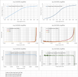
This is how my JLH1969 built about 45-47 years ago measures today (I am in the process of verifying the performance of my amplifiers)Wonderful to see revived interest in J. L-H.'s design and that it has stood the test of time.
Simple designs are often the best!
BC212 (Siemens), BC 140 (Siemens), 2N3055 (Motorola).
1uF MKT input, 470uF bootstrap, 2200uF output (capacitors are some 15 years old).
1 Ampere per channel at 24Vdc
George
Attachments
-
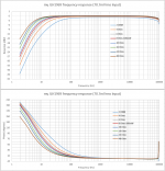 1 JLH1969 FR100mW various loads.png116.6 KB · Views: 283
 -
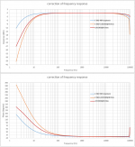 2 correction of FR.png97.4 KB · Views: 261
 -
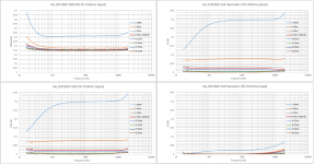 3 JLH1969 THD100mW various loads.png169.2 KB · Views: 259
 -
 4 JLH1969 THDvsPower@4 Ohm.png95.4 KB · Views: 238
 -
 5 JLH1969 THDvsPower@8 Ohm.png96 KB · Views: 232
 -
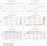 6 JLH1969 THDvsPower@16 Ohm.png92.1 KB · Views: 140
 -
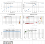
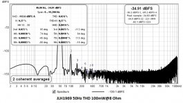 7 JLH1969 50Hz THD 100mW@8 Ohm.jpg115.5 KB · Views: 144
 -
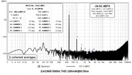 8 JLH1969 500Hz THD 100mW@8 Ohm.jpg115.8 KB · Views: 130
 -
 9 JLH1969 5kHz THD 100mW@8 Ohm.jpg116.5 KB · Views: 154
 -
 10 DSCN5636.JPG647 KB · Views: 220
No need to match o/p pair,as it is asymmetrical,one half is an emitter follower (upper),the other a grounded emitter. Later 2N3055s used the Epitaxial process , giving higher ft.,older ones used the Hometaxial process. A visit to "The Class A Amplifier Site" ,now hosted by Rod Elliott on the Elliott Sound Products web site,is well worth while. There is an update (Sept.1996) by the Great Man himself on improvements to the original design,plus constructors' personal experiences and improvements. If you intend to build a pair of amps. using your proposed transistors ,construct in such a way that the output transistors can be changed easily,in case the results are disappointing . Don't forget ,there have been massive advances in transistor technology ,with much better devices being available.I built a J.L-H. with Toshiba 2SC5200s*,the amp sounded far too "Bright",not surprising as the freq. response was still flat at 250 KHz.! Sanken make a widely used range of audio power transistors with multiple emitters ,worth considering.
* BEWARE OF FAKES! Buy from reputable dealers only!
Hood makes it pretty clear in his original article regarding the arrangement of gain for Tr1 and Tr2. He even includes a chart showing his experiments. Matching is best, but if you don't have a matched pair then higher gain part should be in Tr1. Hood uses the word "necessary". I feel like I should take his advice.
I have read recommendations from many sources about how the 2N3055 is a crappy part and there are much better options (page one of this thread is an example). I don't doubt it at all (relative to modern parts) but I am getting nostalgic as I age and I want to build the original. I like the simplicity of the single supply architecture. Also, I have 12 2N3055s in my bin and want to use some of them. If I had MJ480s I'd be using them.
The goal is to build, learn and listen - not make an award-winning amp. 🙂
If my amp performs anything like gpapag's on the previous page, I'll be perfectly happy.
Last edited:
This amplifier is not so powerful - you can use different output transistors - I use plastic BD911 - they work great. it all depends on what heatsinks you have - to3 pre- drilled or simple flat ones
I only want/need a handful of watts. My SET makes me happy with 6 or 7 watts and I normally use less than 2 watts.
I have TO-3 pre-drilled aluminum angle brackets that will be bolted to heat sinks.
I have TO-3 pre-drilled aluminum angle brackets that will be bolted to heat sinks.
Hood makes it pretty clear in his original article regarding the arrangement of gain for Tr1 and Tr2. He even includes a chart showing his experiments. Matching is best, but if you don't have a matched pair then higher gain part should be in Tr1. Hood uses the word "necessary". I feel like I should take his advice.
I have read recommendations from many sources about how the 2N3055 is a crappy part and there are much better options (page one of this thread is an example). I don't doubt it at all (relative to modern parts) but I am getting nostalgic as I age and I want to build the original. I like the simplicity of the single supply architecture. Also, I have 12 2N3055s in my bin and want to use some of them. If I had MJ480s I'd be using them.
The goal is to build, learn and listen - not make an award-winning amp. 🙂
If my amp performs anything like gpapag's on the previous page, I'll be perfectly happy.
JLH specified more recent epitaxial base 3055s - your old RCA and Westinghouse ones in your bin are most likely older hometaxial base types.
This component choice was by design to make the circuit unconditionally stable without need for compensation capacitors.
The existence of high fT transistors was known to JLH in the early 70's.
The use of 2SC5200, a more recent device, did not work out for Alan Frobisher because this resulted in a "too Bright " sound.
mjona; said:JLH specified more recent epitaxial base 3055s - your old RCA and Westinghouse ones in your bin are most likely older hometaxial base types.
This component choice was by design to make the circuit unconditionally stable without need for compensation capacitors.
The existence of high fT transistors was known to JLH in the early 70's.
The use of 2SC5200, a more recent device, did not work out for Alan Frobisher because this resulted in a "too Bright " sound.
I did some experiments where I had one side (one channel) with TIP35C and the other channel with 2SC5198. Then I switched to one side (one channel) with D1047 and the other channel with TIP35C.
I was expecting dramatic differences between the output transistors... ...but I found greater differences from the driver and capacitors. I was not expecting that considering how different those three types of output transistors are. (Especially the TIP35C.) The TTC004 driver instead of the TIP41C was the more influential transistor in my little experiment.
I try to do all my experiments now so that there is no time gap between comparing "X" with "Y". For example, if I am comparing the PCM1704 DAC to my new AK4396 I do it with the RX-Z1 (with the PCM1704 inside) so that I can switch between the PCM1704 and the AK4396 in 1 second with the signal source button. That way I can go back and forth between the two (and repeat tracks and sections of tracks) again and again without gaps of hours or days between tests. That way my "ears"/hearing and all the other equipment and environment are constant.
In the past I might listen to "X" for hours or days and then modify or reconfigure and listen to "Y" for hours or days and often conclude there was a difference. However I find some of the "differences" much harder to find when I eliminate the time gaps and ping-pong switch between two identical amplifiers (with only one change such as different output transistors) or as a different example two different DACs (with everything else constant).
I think the quick (seconds) ping-pong switching is essential because "ears" and hearing seem to "change" too much from day to day.
JLH specified more recent epitaxial base 3055s - your old RCA and Westinghouse ones in your bin are most likely older hometaxial base types.
This component choice was by design to make the circuit unconditionally stable without need for compensation capacitors.
I can't find where JLH himself recommended epitaxial base 2N3055 for the 1969 version, but I do see it in the notes on substitutions here The Class-A Amplifier Site - Transistor Substitutes I had failed to notice that before. I wonder if that is specific to 2N3055 being used in the 1996 version, or true for both versions.
So I am S.O.L. with these vintage RCA and Westinghouse? Not even worth trying?
I don't mind switching gears at this point, since nothing is built yet, but I'll probably just source some epitaxial base 2N3055s. So much of the info available is about the 1996 (or variations of that design), even in this very thread, that I need to be vigilant about staying focused on the 1969.
Last edited:
I did some experiments where I had one side (one channel) with TIP35C and the other channel with 2SC5198. Then I switched to one side (one channel) with D1047 and the other channel with TIP35C.
I was expecting dramatic differences between the output transistors... ...but I found greater differences from the driver and capacitors. I was not expecting that considering how different those three types of output transistors are. (Especially the TIP35C.) The TTC004 driver instead of the TIP41C was the more influential transistor in my little experiment.
I try to do all my experiments now so that there is no time gap between comparing "X" with "Y". For example, if I am comparing the PCM1704 DAC to my new AK4396 I do it with the RX-Z1 (with the PCM1704 inside) so that I can switch between the PCM1704 and the AK4396 in 1 second with the signal source button. That way I can go back and forth between the two (and repeat tracks and sections of tracks) again and again without gaps of hours or days between tests. That way my "ears"/hearing and all the other equipment and environment are constant.
In the past I might listen to "X" for hours or days and then modify or reconfigure and listen to "Y" for hours or days and often conclude there was a difference. However I find some of the "differences" much harder to find when I eliminate the time gaps and ping-pong switch between two identical amplifiers (with only one change such as different output transistors) or as a different example two different DACs (with everything else constant).
I think the quick (seconds) ping-pong switching is essential because "ears" and hearing seem to "change" too much from day to day.
At some stage in the history of the Simple Class A Amplifier JLH suggested an option making Tr1 a Darlington transistor an MJ3001.
I don't have the documentation with me away from home but my memory of the context is that move would improve THD significantly and one need not worry about matching the gain of 2N3055s.
Most At some stage in the history of the Simple Class A JLH suggested an option making Tr1 a Darlington transistor an MJ3001.
I don't have the documentation with me away from home but my memory of the context is that move would improve THD significantly and one need not worry about matching the gain of 2N3055s.
With either the 1969 or the 1996 one, I am not aware of anyone having experimented with this change.
I can't find where JLH himself recommended epitaxial base 2N3055 for the 1969 version, but I do see it in the notes on substitutions here The Class-A Amplifier Site - Transistor Substitutes I had failed to notice that before. I wonder if that is specific to 2N3055 being used in the 1996 version, or true for both versions.
So I am S.O.L. with these vintage RCA and Westinghouse? Not even worth trying?
I don't mind switching gears at this point, since nothing is built yet, but I'll probably just source some epitaxial base 2N3055s. So much of the info available is about the 1996 (or variations of that design), even in this very thread, that I need to be vigilant about staying focused on the 1969.
The short answer is you can take that as relevant to both versions of the amplifier. With 2N3055 the split phase driver needed 2N1711 to replace 2N1613 for the same performance as the original.
I have the relevant stuff at home. I am at our beach holiday property at present.
Mjona: I have turned a subtle shade of green! On the Beach? I am stuck in the cold ,damp Fens of East Anglia, freezing fog outside (temp. -0.9 C ). All the best with the amps.Ultimately it is which design sounds best with your speaker and listening room arrangement.
Famous British amplifier Alto (Audio Innovations) on a modified JLH1969 circuit. It is built using discrete Darlingtons. Works in AB class.
The manufacturer's recommended quiescent current is 140mA. Output power 35w/8ohm.
http://forum.vegalab.ru/attachment.php?attachmentid=387839&d=1609945455
The manufacturer's recommended quiescent current is 140mA. Output power 35w/8ohm.
http://forum.vegalab.ru/attachment.php?attachmentid=387839&d=1609945455
Last edited:
- Home
- Amplifiers
- Solid State
- JLH 10 Watt class A amplifier