I was looking at the price of these out of interest.
A 1.5mH choke 5A 70milliohms $22aud. I'm assuming here that this would be suitable spec.
Don't buy these they are too big, too dear and if my recent experience is anything to go the stocks will be held in America and you will have to pay as much or more to get them shipped as the asking price of $22aud.
The ones I used were purchased from Jaycar at a cost of $8.60nzd - they will cost less that than in aud see 470uH Prewound Ferrite Choke | Jaycar Electronics New Zealand - these are powdered iron not ferrite as shown in the catalogue and the link.
I used these with 30,000uF and there is no sound coming from my speakers with the chokes interposed between the bridge rectifier and the supply banks. You can expect the same result if you take care to avoid earth loops.
If there is any hum, or white noise as a mentioned in a recent contribution about switch mode power supplies, these are signal artifacts that were not present in the input signal.
The signal artifacts will be summed with the feedback from the loudspeaker and the result fed back from the output via the feedback loop. The resultant sound will be better without these impediments.
I have some 500 uH 3A chokes. When I get a chance I will redo my RC filter test. I think it will be interesting. One of my halogen lamps stopped working. I will redo using fixed resistors. 15 VDC 1.2 A. If using twice the amps the hum is proportional and worse. 1.2 A should suit the chokes.

If you notice the 500 uH is marginally worse than the resistor. Noise drops at RF.
500 uH at 100 Hz is Xl = ( 2 x 3.142 x 100 x 500 )/1000 000 = 0.3142 Ohms.
These chokes are for SMPS. At 100 Hz, chokes were used with an iron plate core, like a transformer 50-150 W. Inductance 1-10 H.
Usually LC or CLC.
Usually LC or CLC.
Last edited:
The Class-A Amplifier Site - Updated Power Supply
I am just looking at this "updated, regulated power supply for the 1996 version" from the Class A amplifier website.
The JLH 1996 uses a bipolar power supply, and the rails are labelled +22V and -22V on the circuit diagram - but isn't the LM338 a positive voltage regulator? How is it possible to get -22V from this regulator? As far as i'm aware there aren't any 5A rated adjustable negative voltage regulators commonly available.
Bottom source of similar polarity with separate winding and bridge. Connected in series (+) to ground. It turns out (-).
Make the transformer at least double the rating you would imagine. Although it's very hard to prove the transformer being big is a sonic advantage. It's tempting to think the inductance helps.
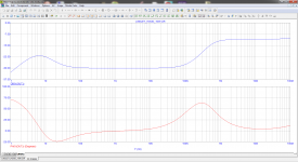
The 500 uH choke is circa 0.3R at 100Hz. Even at 1000 Hz that's only 3R. It's more complicated than that as some will realise ( not in a helpful way ). If you look at my graphs nothing is happening to the sawtooth and that makes for a slightly harsh sound and likely some hum. That choke I used is not silly money. It will be useful > 10 kHz and one is enough. iC = CdV/dt Where iC for us was 1.2A C 52 000 uF and dT relates to 100 Hz in mS . Thus dV for my example is 230 mV if no filter applied. It would be fair to say a 500 uH choke isn't the answer. 1H is 1000 000 uH. 630 ohms at 100 Hz. If wondering a bridge rectifier converts 50 Hz to 100 Hz by making each wave positive. 120 Hz USA. If using low power and a regulator you can try a primitive rectifier as it might sound better as it will be 50 Hz. If so use a soft diode. For opamps it could be OK.
The reason this type of filtering is not ideal is that ideally a filter is bounded by an infinite impedadance. Very easy to do close to that when an op amp filter. I was very dissapointed but not surprised by the 1R5 10 000 uF filter as it's starts below 25Hz on paper ( 10 ). It should be 12 dB down at 100 Hz. That's 36 dB total. As seen it's far less ( < 10 dB ).
Here is the choke tried. Exceptional for making simple switch mode USB to up to 24VDC ( NE555 and BD139 66 kHz ). Even sounds good. It is about 200 ohms at that frequency. It shoud be said that 200 ohms of a choke is not identical to 200 ohms of a resistor. Near enough to know it might work.
Electroustic 1585 500uH Axial Suppression Choke | Rapid Online
If you look at my first example it is very low cost and state af the art if not OCD about things none can hear. The LD1084 in my mind is not so easy to do if wanting +/- PSU. If anyone wants to see how to do that I will draw it. It might be too tricky for some.
Battle through this. It also says less can be more.
DC Power Supply design
BTW. All of this I stopped doing in 1974. I get surprised how much we just guess because it's good enough until doing basically pure 1930's power suppliers as here. Diodes of this type were devices of the 1880's made of selemium. British motorcycles of the 1960's used them. They were not so different. Smell cabages and run as it's dangerous. One could if the man Tesla be doing this in 1890. He would have to infer ripple as there were no oscilloscopes. Quad ESL diodes were selenium I am told.
When I say stopped doing it is like a train journey where I see the station but don't get out. This time I did and it you like there is a village of questions behind the station.
When I say stopped doing it is like a train journey where I see the station but don't get out. This time I did and it you like there is a village of questions behind the station.
This is a bargain. It's a JFET constant current source. It can be used with a zener didoe and very high gain Darlington make a 1974 regulator.
ATC Semitec E-202~E-562 Current Limiting Diode CRD - 2.0mA | Rapid Online
ATC Semitec E-202~E-562 Current Limiting Diode CRD - 2.0mA | Rapid Online
This looks like it shouldn't work. It works quit well. The voltages add like batteries. There is a tiny bit of compound noise doing this. If you notice 18VAC roughly is OK for 18VDC. This circuit could give more volts. It's easy to find out. 1K8 instead of 1K6 gives 20V. I have never built this exact circuit but have using the similar LM317. An extra bridge rectifier required to do this. Some didoes from the data sheet required. 22 000 uF will help you get the most from the LD1084 is ripple rejection and higher voltage. A 25 VAC transformer is slightly too high I feel. Use 18 VAC and get what you can from it dependant on local mains voltage ( I have 238 to 244 ). 15 VAC if wanting less. > 225 VA transformer size I would say. 180 VA if much cheaper. Ignore the parts. That was a LM317 version.

I am considering going with the LM338 design from the Class A site. I'm using a 18+18VAC transformer so might not get 22V out. My brindge rectifiers take 1.1V out. Would best approach be to measure Vin at the LM338 and adjust resistors to get the recommended 3V drop?
I am tempted towards the LD1084 for the lower voltage drop (?1.5V). Shouldn't you be able to get 22V from 18VAC even with losses? My concern is that you hear tales about them being prone to oscillation and my layout on perf board might not be ideal.
If running at less than 22V, is it best to keep current setting the same and just have less power?
You might find at the real load the rectifier is more, could be at least 3V. That double LD1084 is a tricky idea. The speaker current flows through the OV terminal so has a complex path. It's nearly a vitual 0V rather than the hard 0V of a simple type using one rectifier.
What I should do is build you a double NPN PNP darlington PSU using BD139/140 TIP35/36 zener diodes and JFET current source that look like diodes. Should be no worse than many regulators and can be faster types. A resistor is an alternative to the JFET. Darlingtons seldom do bad things like oscillate. This idea is not any more complex .
The difference we hear between 7 and 20 watts is small. 1 amp is already good at 14 volts +/- ( 28 V 1969 design ). A class A amplifer has greater dynamic range so sounds more powerful . That's how our ears work. A larger transformer seems to have deeper bass. When I was 30 I knew exactly why. Now I don't.
What decrease do you refer to? For example, the harmonising of European (220V) and UK (240V) mains supplies had no effect on the actual supply voltages - just how the voltage tolerances are defined.
I always try to get my designs to work at. 207 vac. 190 vac was allowed in Belgium before the harmonization. I get 236 to 244 vac and I would hate that to change as it's a low distortion supply.
I am going to buy some TIP142/147 Darlington's. 10. amps and cheap. I suspect that they are marginally better than a voltage regulator for speed and have a built in protection diode. I won't post this until happy it works. With class A amplifiers if it works today it should forever. This is close to JLH. I built a CV simple 7815 7915 PSU yesterday. It drives me bonkers that the tag isn't zero volts on both. This idea is to have it as simple as possible. I will use 207 to 253 vac. 207 has tightened of late and should be about 215 vac now. House wiring is allowed quite a drop also.6 vac would be allowed but unlikely. In a rush so correct any typos.
I am going to buy some TIP142/147 Darlington's. 10. amps and cheap. I suspect that they are marginally better than a voltage regulator for speed and have a built in protection diode. I won't post this until happy it works. With class A amplifiers if it works today it should forever. This is close to JLH. I built a CV simple 7815 7915 PSU yesterday. It drives me bonkers that the tag isn't zero volts on both. This idea is to have it as simple as possible. I will use 207 to 253 vac. 207 has tightened of late and should be about 215 vac now. House wiring is allowed quite a drop also.6 vac would be allowed but unlikely. In a rush so correct any typos.
OK, I see you mean the legal requirement for the power provider's supply voltage. In my location, I seldom see more than 1.0% variation when I check this, even though most homes in my area now reverse-supply the grid during daylight hours to receive credit for their excess generated power. Fortunately, the local supply control is such that there is little or no significant supply voltage variation from full sun to dull or dark conditions.
I have a supply monitor device fitted in the power strip on my workbench so checking the supply is simply a matter of looking at the energy monitor meter as I take voltage readings against those in the service manual. For others, it wouldn't be expensive to fit a a cheap in-line plug/socket energy monitor to their power supply and be able to read off more than they need to know without burning out their budget DMM or having to make probe contact with mains voltages (don't do it ). Absolute accuracy is not essential here; variations are of more interest.
I have a supply monitor device fitted in the power strip on my workbench so checking the supply is simply a matter of looking at the energy monitor meter as I take voltage readings against those in the service manual. For others, it wouldn't be expensive to fit a a cheap in-line plug/socket energy monitor to their power supply and be able to read off more than they need to know without burning out their budget DMM or having to make probe contact with mains voltages (don't do it
). Absolute accuracy is not essential here; variations are of more interest.Thanks again for all the advice everyone. Learning lots.
I have been reading about LM723. It has low current rating and would have to be used with a transistor but seems to have similar ripple rejection to LM338 and is very low noise (microvolts). I haven't really come across any power supplies based on this IC. Is isn't new - has anyone used this.in a low noise psu that would Class A amps? Is it worth the extra complexity over say a LM338 without transistor?
I have been reading about LM723. It has low current rating and would have to be used with a transistor but seems to have similar ripple rejection to LM338 and is very low noise (microvolts). I haven't really come across any power supplies based on this IC. Is isn't new - has anyone used this.in a low noise psu that would Class A amps? Is it worth the extra complexity over say a LM338 without transistor?
- Home
- Amplifiers
- Solid State
- JLH 10 Watt class A amplifier