#6740
1.Voltage stabilization is the main function of the linear regulator.
2. Current limiting protects the regulator and amplifier from damage.
3. Adding a voltage regulator to the capacitance multiplier limits the output voltage when the mains voltage is exceeded.
4. A pair of Shiklai has less voltage drop.
5. The filter after the bridge provides a certain level of ripple.
In the 1996 article, there is a statement regarding the voltage regulator in the updated power supply:
The circuit shown for the current booster pass transistors,TrJiTr2, is one suggested by National Semiconductor. It takes advantage of the internal current limiting circuitry of the 7815/7915 devices to limit theshort-circuit current of these ICs to 1.2A. By choosing the correct ratios of RS:R7 and Rg:RIO, the shortcircuit current drawn from Trl and Tr2 will also be limited.
Was this the reason for including it, or just an perceived added benefit.
Was it inlcuded primarily to stop mains voltage fluctuations (I thought this was generally not required for amps).
I don't really understand this and am a bit puzzled why it is necessary to have a voltage regulator in the design (keep in mind I am just learning!). Would having one in there also mean that you would not be able to set the quiescent current above 1.2A?
I doesn't seem to be usual practice to include a regulator in a capacitance multiplier - just an RC filter and a transistor (or pair) to take most of the current away from the RC filter. A regulator can follow obviously if voltage regulation is required. I didn't think that voltage regulators added much of a reduction in ripple and noise. Rod Elliotts design doesn't include one. If I understand correctly, his version seems to add an addition RC before the transistor and remove the regulator.
Is there a preferred transistor arrangement for this type of load - Darlington pair, Sziklai pair, or MOSFET?
Taking the last point first the supply circuit figure 5 shown on page 687 of the Electronics World Article will allow enough current for 15W into 8R the bypass transistors will pass part of the current demand 4A for two channels. The bypass devices are not Darlington types.
The 7815/7915 regulators use negative feedback to regulate the voltage and reject ripple on the supply rails. All semiconductors have some internal noise -I cannot hear any at all with my ear pressed against the loudspeakers.
There has been some confusion over the mention of Up-grade the smoothed but not regulated power supply. The meaning of this is to make the capacitance multiplier redundant by building the circuit in figure 5.
I built the 1969 circuit in 1976 and about that time I had visited a High Street Hi-Fi shop and heard a demonstration of the then new Naim NAP250 connected to a Linn loudspeaker.
That amplifier uses a regulated power supply for each channel and the difference in the bass response compared to my 1969 JLH was palpable.
At the time I reasoned that the difference was to the time constants in the capacitors being insufficient so I increased all the values.
I had not appreciated at the time the Naim amplifier supply impedance was lower and so changing these capacitors was a waste of time and money.
If you want to be able to follow bass lines in music better that will improve the listening experience across the board. The sound will appear more integrated - musicians playing in time etc.
I am still using the 1996 JLH which I built in that year complete with the regulated supply in addition to 30,000uF in each supply rail. To this I incorporated some powdered iron chokes between these capacitor banks and the bridge rectifier to further reduce ripple and noise from the supplies.
This made an unexpected and sizeable improvement in the sound.
Last edited:
The input voltage of the linear regulator must take into account the ripple, mains fluctuations (-), the minimum voltage drop across the regulator. So that there is no noise at low mains voltage.
The linear regulator can be excited at RF frequency if the installation is faulty (excitation amplifier).
The linear regulator can be excited at RF frequency if the installation is faulty (excitation amplifier).
Last edited:
I am still using the 1996 JLH which I built in that year complete with the regulated supply in addition to 30,000uF in each supply rail. To this I incorporated some powdered iron chokes between these capacitor banks and the bridge rectifier to further reduce ripple and noise from the supplies.
This sounds like a strong endorsement for the 1996 design as published plus a choke. 30000uf per rail I can definitely handle.
AllenB also mentioned a choke as being a good starting point.
Could you point me in the direction of something to use here? Did you wind your own? What is a suitable value?
Thanks everyone for all of the helpful info.

This is perhaps a better idea. About 18 dB better hum than a typical switch mode ( Meanwell ). Hiss is higher than I guessed. The idea here is to keep heat loss to a minimum. The 1K can be repalced by a constant current source and the zener by a resistor if you prefer. Doubtless 1K can be bettered.
If the outputs are tough a simple fuse is a good protection. The idea is easilly made opposite if you want opposite output polarity, reverse the zener if so. BD139/140 and TIP35/36 ( very tough ) are good places to start. The voltage loss here is almost that of a single transistor except the current gain is massive. This means the ripple at the zener is minimal. A little hiss is not a problem, it's better than SMPS.
Chokes cost a fortune. If you look at the previous example 90 000 uF and at about 1.2A the ripple is still a problem. I had that capacitors for years as a freebe if wondering. 82 dB down ( - 82dBV ) is about 1/10000V at 100 Hz. Slightly more if an advertising man.
A resistor is a viable alternative albeit you need a few. 1R 17 watt will be cheap and have a small bit of inductance which is no bad thing for this. 1R 2 A is 2V loss. I think 22 000 uF 1R 10 000 uF 1R 10 000 uF 1R 10 000 uF could word ( not for class AB or D ). It will get hot and not regulate the voltage. I am tempted to say it's a reasonable idea. The corner frequency is 16 Hz so at 100/120 you get 30 dB total.
I have built more PSUs than people have had holidays. The more complicated they are the more you need a lifetime in electronics to get them to work. A slightly defective PSU will ruin the sound. I am working on a cheap PSU right now. It sounds chromium plated. At first it's great ..... Whist it's hard to prove the larger transformers often sound better. Preamps with 500VA types can work well, not an expensive option when having them anyway ( Naim Audio ). I have no real idea why they sound better, when younger I thought I did. Most concepts of transformers fail why measurements done.
Maybe especially with class AB amps? I think even extra capacitance can't make up for an insufficient power transformer.larger transformers often sound better.
I have wound my own, but there are sources of usable chokes. Sometimes old power transformers. Resistance is a factor, no less for powering an SS class A power amp.Could you point me in the direction of something to use here? Did you wind your own? What is a suitable value?
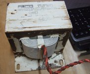
Lighting ballasts are a good source and I have many for various purposes. I happen to have a pair of these (pictured) which I currently use. I'm sure I don't need them to be this large but they work well. Resistance is 1/4 ohm, L is 100mH.
Attachments
The chokes I used were inexpensive types used for EMI suppression rated at 5A - with 470uH of inductance and 82milliohms resistance. The purpose in using these is to blunt saw tooth elements which arise in rectification of the secondary a.c. output of a transformer. I was able to incorporate these as the custom made toroidal transformer I used gave unregulated supply rail voltages of 30V - exceeding the level of 27V mentioned by JLH.
The whole supply including the transformer was generating a level of heat I was of some concern - particularly the booster transistors. I thought it better to use the chokes to absorb some of the heat - these do get very hot.
Toroidal transformers have some mechanical noise a buzzing sound if the loading is too heavy. This had been experienced in some kits for a Class A amplifier published in Silicon Chip magazine.
There had been some reported instances of this from builders living in remote areas of Australia. I did not have this problem however such mechanical noise as there was is less audible since including the chokes.
There is no need to go over the top with lighting ballast chokes and the like.
Too much capacitance and a small transformer can sound boomy. Usually a larger transformer is worth trying. My slightly modified NAD 3020 has only 2 x 1200 uF high grade. It's my workshop amplifier that often is my house amplifier. The smaller caps definitely helped the sound. I remember old Kenwood amps were about the same values and sounded very sweet. These capacitors have a high ripple current and excellent tan theta. High voltage caps often do. The caps were very cheap from CPC. Maybe no one wants that value? Panasonic I think.
I hope people realised the zener example I showed is likely to be superior to the capacitance multiplier. Even with the massive 90 000 uF the initial hum is -46 dBV and only drops to -82 dBV. Less than 40 dB or 100 fold reduction.
I hope people realised the zener example I showed is likely to be superior to the capacitance multiplier. Even with the massive 90 000 uF the initial hum is -46 dBV and only drops to -82 dBV. Less than 40 dB or 100 fold reduction.
I had a big tidy up and think I have enough parts to do an RC power supply. I am interested to know how well it will work. Being cascaded filters the outcome can be less than some might think. Chokes work well with valve circuits where current is low and voltage high. For example an EL34 push pull amplifier of similar watts as JLH would use 130mA per channel. As the Dynaco it gave more watts.
I built the 2005 Geoff Moss Version. Have two Lenovo laptop bricks paralleled 2* 20V as power symetric supply and with this loading 20.000 uF capacitors as buffers. 4A current, 2 ohm magnetostat as speakers. The capacitors are loaded with an ntc with 10ohm in front so that it works out with the bricks. ..you need to go as close as 5cm to the speaker to sense something like white noise. Fair enough for me. Cheap, efficient, quiet and stable power supply! ..dont know why there should be anything wrong with smps?
Last edited:
It's an old tradition and also, many builders are newbies, inspired more by John Linsley Hood's appealing and informative articles, as much as having a need for another amplifier. This results in some builders still duplicating the prototype build style and the point-to-point wiring, even though superior, cheap PCBs and full parts kits have been available for near 20 years.
SMPS wasn't an option 50 years ago so nothing is mentioned of it in the articles. Instead, JLH suggests complex, discrete linear regulated supplies but most folk would have been scared off by the cost and settled for a simple, unregulated transformer/rectifier supply, knowing by popularity that this can sound excellent too.
SMPS wasn't an option 50 years ago so nothing is mentioned of it in the articles. Instead, JLH suggests complex, discrete linear regulated supplies but most folk would have been scared off by the cost and settled for a simple, unregulated transformer/rectifier supply, knowing by popularity that this can sound excellent too.
It's an old tradition and also, many builders are newbies, inspired more by John Linsley Hood's appealing and informative articles, as much as having a need for another amplifier. This results in some builders still duplicating the prototype build style and the point-to-point wiring, even though superior, cheap PCBs and full parts kits have been available for near 20 years.
SMPS wasn't an option 50 years ago so nothing is mentioned of it in the articles. Instead, JLH suggests complex, discrete linear regulated supplies but most folk would have been scared off by the cost and settled for a simple, unregulated transformer/rectifier supply, knowing by popularity that this can sound excellent too.
I can't speak for others but I haven't really been inspired by articles by anyone. I was going to build a Le Mostre but changed my mind mainly due to the amount of support available for the JLH. I have developed an interest in electronics in general and felt that a project that matched in with my love of music would be rewarding. I have already built a music streamer using a SMPS, raspberry pi, DAC and pre-made Class D amp board. I didn't learn much as I already knew how to connect two wires together and cut aluminium sheet. This project is more about learning than the need for another amplifier. I am not planning on using point to point wiring because I think it will be cheaper or easier or sound more authentic. It is so I can practice translating a schematic into an actual circuit. As far as the type of power supply, people are often very divided as to which is better. Class A amps are very inefficient so I don't really see the point in using a SMPS for its efficiency. There are other benefits I know, but I would also like to better understand the various ways in which I can build a low noise power supply other than using a very large bank of capacitors which, as you point out, was the only real option in 1969.
I am yet to find a simple fool proof method for filtering the high frequency switching noise from SMPS. I have nothing against SMPS though. They are quite comparable in cost, so how they are not used more by high end commercial amplifier manufacturers?

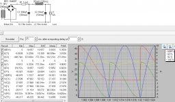
What a waste of money this would be. I used a Variac to get a quick result. Ian Finch would like me to point out that Variacs like motorcycles are dangerous. 204 VAC worked.
I was a little surprised it met my worst expectations.
Look at the resisdual. It's still a sawtooth and has the classic odd and even harmonics ( triangle waves are just odd harmonics ). One of the downsides of a large capacitor is the sawtooth is still how it looks.
You migh ask yourself this question. How come class AB don't need this ( or do they ?).
The idle current can be as low as 10 mA if the Quad 303. That means zero volume hum is low. The music masks the hum or maybe not really. The Quad has a regulated PSU so they thought like me. Modern class AB amplifiers work like a voltage regulator in themselves. As long as the music to the power trnsistors is hum free the amplifer has no need for extra regulators. In many ways class AB is the only logical choice. Don't read experts on them as I never read one who truely knew the problems. Basically music isn't what they use for testing.
Even if you have vast amounts of money chokes don't really help. I dare say the JLH can reject some power rail noise. Someone might know how much. I doubt enough to work with this idea.
BTW. The oscilloscope agrees with the spectral graph. If using a regulator don't use RMS values as you need peak to peak. The lamps are tough and cheap. I calibrated them first on a lab PSU.
Yes. It can be many times more. Old style halogen lamps are great loads as they are designed to run hot. They are non linear so need to be calibrated. The cold resistance of the these two lamps is 3.6 ohms. 15.2^2/3.6 = 64.18 watts when reality is 18.24 watts. The 12V ( 2 if 24 V ) is 7.2 ohms. The cold hot ratio would be 80/20 watts and actually is on start up. Less so if a transformer is between the mains and the lamp as it also comes to voltage over perhaps 50 mS as the core charges. The late Andrew T and I came up with that. It is seen as the opposite of a decaying wave.
Some companies used this and a 500 uF non polar capacitor as a speaker protection device. Test engineers often use an old fashied mains voltage lamp in series like a fuse as a current limiter. If the lamp comes on bright you are in trouble. It also saves destructive meltdown.
Some companies used this and a 500 uF non polar capacitor as a speaker protection device. Test engineers often use an old fashied mains voltage lamp in series like a fuse as a current limiter. If the lamp comes on bright you are in trouble. It also saves destructive meltdown.
The chokes I used were inexpensive types used for EMI suppression rated at 5A - with 470uH of inductance and 82milliohms resistance.
I was looking at the price of these out of interest.
A 1.5mH choke 5A 70milliohms $22aud. I'm assuming here that this would be suitable spec.
156B Hammond Manufacturing | Mouser Australia
Equvalent to cost of about 30000uF of good quality caps
UKT1V103MRD Nichicon | Mouser Australia
Here is an example choke input supply (ignore the first capacitor, it is too small to be filtering). This supply gives 26mV of clean sinusoidal ripple.. so LC alone is just about quiet enough to use. In addition I like to take an RC to each stage for multiple reasons.. so I can easily get the ripple down to the milliVolt level without resorting to regulators.The purpose in using these is to blunt saw tooth elements
Attachments
..... They are quite comparable in cost, so how they are not used more by high end commercial amplifier manufacturers?
Most popular Chinese audio products like HT amplifiers, now use SMPS. You may also know that NAD has been trying to rekindle the stereo audio power market with their tiny D3020 model but I don't think it's broken any sales records or impressed reviewers as did the original 3020 model. The example below is where the mainstream audio market is now and its certainly driven by SMPS: NAD Announces Highly-Anticipated T 778 Flagship AVR is Now Shipping - NAD Electronics
SMPS for DIYs to install, is often sold in the form of metal enclosed, grounded supplies but also as open, unshielded PCB assemblies because they are cheapest but with the hidden cost of mains unsafety; mostly ignored in their promotion. It's extremely unwise to play with open SMPS assemblies though seldom any problem with those fully insulated brick types or metal housed, grounded types that become necessary for use with 100W + apps, where temperature becomes a problem for the plastic housing and capacitor lifetime.
The problem with SMPS is mediocure ripple. This is due to small high voltage capacitors before the oscillator. 47uF sometimes. The switchmode can improve that ( see power gyrator ciruits ).
Here is the better idea I feel. Being T0220 package I would use two. The zener is 2 dB quieter. The 120R can be experimented with if the zener version. The extra > 10 uF ( 47 uF ? ) helps greatly. Add 1.25 V to the zener voltage. It will be less predicatable than resistors. It will be rock solid once running. See data sheet for protection diodes.

Here is the better idea I feel. Being T0220 package I would use two. The zener is 2 dB quieter. The 120R can be experimented with if the zener version. The extra > 10 uF ( 47 uF ? ) helps greatly. Add 1.25 V to the zener voltage. It will be less predicatable than resistors. It will be rock solid once running. See data sheet for protection diodes.
- Home
- Amplifiers
- Solid State
- JLH 10 Watt class A amplifier