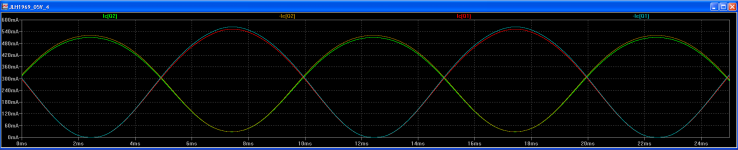
Finally back to measuring the total current drawn by my version of the JLH '69 (+5V supply 0.5W output into 4R load)...
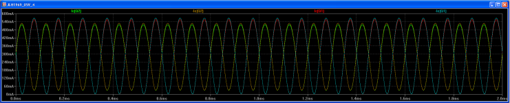
The screenshots below show the current draw of a 100Hz and then a 10K Hz sine wave across the collector and emitter of the two output transistors (where the highest current draw appears to be).
Is it a correct assumption from this that my circuit is drawing up to approx. 560mA?
Based on that - what should I be looking at as a safe spec in mA for a power supply?
My initial target of running it off a 200mA wall wart was apparently way off!. (Edit: double-checked and the wall wart I was looking at is running at 500mA [new Boss PSA240 ES] as I originally thought so maybe I'm back in the ballpark?)
Thanks!
Attachments
Last edited:
+5V supply 0.5W output into 4R load
With 5V you could be putting over an amp into 4 ohms.
There's some distance between the rated RMS power and the actual, instantaneous currents supplied.
You should consider biasing to 1/2 amp (at least) per channel to avoid running out of headroom.
What thermal resistance should it have?P.
Thermal resistance is no different from electrical resistance.
Tmax = Tambient + deltaT
deltaT = Rthermal x Pdissipated
You know your max case temperature (from data sheets), you should know you max ambient. And the power being dissipated. Rthermal then falls out.
Thank you for the response. Don't know how well, but let's say that heatsinks are resolved. Surely they fit now on the PCB.
What about issues 1. and 2.?
What about issues 1. and 2.?
Last edited:
1. VR2 is the pot in the schematic you posted.Thank you for the response. Don't know how well, but let's say that heatsinks are resolved. Surely they fit now on the PCB.
What about issues 1. and 2.?
2. not sure, personally.
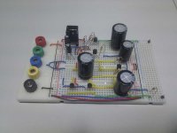
Breadboarded the JLH '69 today for the first time after spending quite a while in sim.
It's running off +5V (deliberately going for something small/low power to start with) and (because I was impatient) I'm using 2N3904 and 2N3906 for all transistors except the FET input which is a 2N5457.
I haven't done any trimming or fine tuning yet so she's still rough round the edges.
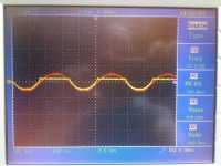
With no load attached I get a reasonable sine wave at the output - but with a 4R speaker or a 10R resistor (or any load below approx. 150R) - the gain drops considerably and the top half of the waveform disappears.
Can anyone give any clues as to what might be causing this so I can start troubleshooting?
Thanks - pic of my breadboard attached for giggles.
It's running off +5V (deliberately going for something small/low power to start with) and (because I was impatient) I'm using 2N3904 and 2N3906 for all transistors except the FET input which is a 2N5457.
I haven't done any trimming or fine tuning yet so she's still rough round the edges.
With no load attached I get a reasonable sine wave at the output - but with a 4R speaker or a 10R resistor (or any load below approx. 150R) - the gain drops considerably and the top half of the waveform disappears.
Can anyone give any clues as to what might be causing this so I can start troubleshooting?
Thanks - pic of my breadboard attached for giggles.
Attachments

Member
Joined 2009
Paid Member
I can't tell - but looks like you're running out of current / voltage headroom due to the power supply being inadequate.
2N3904, 06 have a maximum collector current of about 0.2A therefore not suitable for your application. Do you have something more robust, ex TIP41
2N3904, 06 have a maximum collector current of about 0.2A therefore not suitable for your application.
Would that explain the output working with no load but not with load? The 3904/6 did simulate OK although I do realise they're far from the best spec for the job.
Thanks.
Help troubleshooting please, 2005 version
Hi,
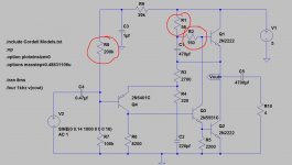
I have been trying for a few days to fix the first channel of the Siliconray JLH 2005 version.
I have used lower rail voltahe of +- 14Vdc to get about 10W at the output.
I have attached the schematics I'm using. The voltage in red are the one when a load of 8 ohm is connected. If I remove the load the voltage on the base of Q4 goes up to 2Vdc.
I can't get the amp to bias at all. I suspect that Q3 or Q4 can be the issue. Replacing a transistors on this board will be a PITA because the contact are way too small and heating the contact will probably destroy the copper on the PCB.
At first glance what could cause this...when I connect a 8 ohm load I get 10.3Vdc at the output and some good current cause the load is heating up nicely. I can vary the bias via VR2 but Q1 and Q2 stays cold..
Any help would be greatly appreciated.
Thanks,
Eric
Hi,
I have been trying for a few days to fix the first channel of the Siliconray JLH 2005 version.
I have used lower rail voltahe of +- 14Vdc to get about 10W at the output.
I have attached the schematics I'm using. The voltage in red are the one when a load of 8 ohm is connected. If I remove the load the voltage on the base of Q4 goes up to 2Vdc.
I can't get the amp to bias at all. I suspect that Q3 or Q4 can be the issue. Replacing a transistors on this board will be a PITA because the contact are way too small and heating the contact will probably destroy the copper on the PCB.
At first glance what could cause this...when I connect a 8 ohm load I get 10.3Vdc at the output and some good current cause the load is heating up nicely. I can vary the bias via VR2 but Q1 and Q2 stays cold..
Any help would be greatly appreciated.
Thanks,
Eric
Attachments

I suspect that Q3 or Q4
you've got 11V Vbe on Q4 and 25V Vce. And Ice=0. It's toast. The smoke is out.
Thanks. Is it toasted because Vbe is too high ? These are rated 125V for Vce.
I tried the second channel and this is what I get for Q4
Vc : -14V
Vb : 0V
Ve : 1.62V
So 1.62V Vbe and about 15.6 Vce. This channel is much better but I still can't bias the amp.
Any other idea ?
Thanks a lot !
Eric
I tried the second channel and this is what I get for Q4
Vc : -14V
Vb : 0V
Ve : 1.62V
So 1.62V Vbe and about 15.6 Vce. This channel is much better but I still can't bias the amp.
Any other idea ?
Thanks a lot !
Eric
If you measure the voltage across the B and E junction of Q4 what do you get ? Whatever other faults you may have, you should read around 0.65 volts with the emitter as the more positive terminal. If its higher than around 0.8 as a max and the polarity is correct then there is something wrong with the transistor, either fitted incorrectly, faulty, or not a PNP.
DO NOT connect a speaker when testing the amplifier.
Short the input and leave the output open circuit.
Power up via a bulb tester.
FIRST check.:
Is the bulb lit?
Short the input and leave the output open circuit.
Power up via a bulb tester.
FIRST check.:
Is the bulb lit?
DO NOT connect a speaker when testing the amplifier.
Short the input and leave the output open circuit.
Power up via a bulb tester.
FIRST check.:
Is the bulb lit?
With Class A amp it probably would be lit and pull the voltage down. You would need to alter the amp to draw very little current to successfully use the bulb tester.
How does it go though, when set to minimum ? You would need it below 100 - 200 ma I suspect for the bulb to be out and not limiting the supply.
I have not tried a single ended ClassA amp.
The PP ClassA amps I have tried will start up on a 40W bulb.
If I want to try biasing it up a little I would use a higher wattage bulb after that first safety check.
I have used a 150W bulb for a heavy load start up.
I now have two paralleled bulb holders so that I have the option to add a big bulb alongside the small start up bulb without having to unplug.
If you measure the voltage across the B and E junction of Q4 what do you get ? Whatever other faults you may have, you should read around 0.65 volts with the emitter as the more positive terminal. If its higher than around 0.8 as a max and the polarity is correct then there is something wrong with the transistor, either fitted incorrectly, faulty, or not a PNP.
Thanks for the help.
I have checked all Vbe directly across each transistors, here they are 🙂
Q1: 0V
Q2: 0V
Q3: 0V
Q4: 0.87
Q5: 0.65
Q6: 0.6
Q7: 0.11
Q8: 0.76
The resistors values for R5 and R9 are the ones for the +- 25Vdc version, for my adopted version at +-14Vdc do these resistors values have to be changed ?
Looks like I have a possible issue with Q3, Q4 and Q7
Thanks,
Eric
- Home
- Amplifiers
- Solid State
- JLH 10 Watt class A amplifier