Hi,
The - pin is not connected to earth ground. I actually do not have any earth ground on the amp, both power supply are double insulated (2 prong inlet)
What I noticed in that it's the PS feeding the positive rail that heats up the most.
From the beginning I noticed that the upper output transistors (Q2), the one connected to the positive rail heats up more than Q1 which is connected to the negative rail. Is this something common with the JLH amp ? So it seems that Q2 is drawing more current which explain why its heating more and the positive rail power supply is over heating...(plastic case about 50C)
Question is, why is Q2 drawing more power vs Q1 ? My MJ15003 are matched (hfe).
Thanks guys.
BR,
Eric
Attachments
Last edited:
A couple of things to check.
1) The only way the output transistors can draw unequal current is if there is a DC offset at the output (and there is a load connected). So make sure the voltage at the speaker terminals is below around -/+100mv. Also measure the rail voltages accurately. If one were +16 volts for example and the other -13 volts then assuming say 1.5 amps flowing the upper transistor would dissipate 24 watts and the lower one just 19.5 watts. Maybe enough to "feel" different.
2) Are the PSU's of identical types ? Have you tried swapping them around to see if the heating follows the PSU.
Member
Joined 2009
Paid Member
The only way the output transistors can draw unequal current is if there is a DC offset at the output
or some kind of a.c. flow through the +ve rail, upper device and to ground via capacitors - wonder if something weird going on with the SMPS at high frequencies ?
or some kind of a.c. flow through the +ve rail, upper device and to ground via capacitors - wonder if something weird going on with the SMPS at high frequencies ?
This is why I suggest swapping the PSU's over to see if the problem is consistent or not. Laptop type PSU's vary in how hot they get, I have an old Acer that runs pretty hot, while a Dell one runs almost cold. That is why I wondered if they were both identical types.
This is why I suggest swapping the PSU's over to see if the problem is consistent or not. Laptop type PSU's vary in how hot they get, I have an old Acer that runs pretty hot, while a Dell one runs almost cold. That is why I wondered if they were both identical types.
Both power supply are identical, same model no. same manufacturer. Each of these are rated up to 3.8A and I'm running them at 2.6A
This morning I have swapped both supply and the power supply that was running warm is still running warm (now feeding the - rail) so the issue is not the positive rail or Q2 drawing more current. 1 of the 2 power supply has an issue.
I have just order another one from e-pay to replace the warm one, I hope the new one will run cooler.
Thanks again to you all.
BR,
Eric
Interesting... the plot thickens. It does indeed seem one PSU has a problem somewhere as I wouldn't have though identical models would vary much tbh.
Welcome to the world of built-by-the-lowest-bidder!... I wouldn't have though identical models would vary much tbh.
I buy large quantities of ethernet switches from a "worldwide leader" in networking.
We have about a 1:100 broken-out-of-the-box rate with one (entry level) model. Minimum testing is the price we (all) pay for the (low) price we pay.
Welcome to the world of built-by-the-lowest-bidder!
I guess so 🙂 The thought had crossed my mind that two "identical" aftermarket PSU's for a particular laptop could look identical but be totally different designs internally.
Not something I have studied though 😀
Just measured my laptop PSU.
The PE to -ve measures 988r
It appears that there is an internal connection between the mains side and the output side !
The PE to -ve measures 988r
It appears that there is an internal connection between the mains side and the output side !
Just measured my laptop PSU.
The PE to -ve measures 988r
It appears that there is an internal connection between the mains side and the output side !
Is that a consistent reading (any DVM, leads either way around) ?
There can sometimes be a resistor and cap in parallel for tying 0v to ground in some types of PSU. 988 ohm is an odd value though.
Two handheld DMM and one bench DMM,
Both polarities measured.
All 6 measurements give 988r +-1r
There is a slowness to reaching final reading indicating there is possibly a capacitor needing to be charged.
Both polarities measured.
All 6 measurements give 988r +-1r
There is a slowness to reaching final reading indicating there is possibly a capacitor needing to be charged.
That's very strange. Using different meters and polarities suggests its a "real" resistance. And it 988 ohm, not 988k.
I mentioned earlier that there can be a resistor paralleled with a cap but that's really just to tie the output to ground at hf, the resistor would normally be very high in value such as a 1meg and the cap something like 470pf/5kv ceramic.
I know you can't open a laptop PSU without severely marking it...... very strange indeed.
It could be. Its the only thing that makes any sense from the readings, but not from a safety aspect. You could imagine a one in a million scenario where the PE terminal was connected on its own to live and thus making the output "live" via a 1k.
It is not double insulated, CE marked (and many others) and it is from a reputable manufacturer (ASUS).
It also states "Made in China".
Just as well the Laptop keys are non conducting !
It also states "Made in China".
Just as well the Laptop keys are non conducting !
Yeah 🙂 You might end up being a quick a typist though.
It really does sound like its tied to ground via a 1k. I guess the safety aspect is no different to any other grounded appliance. You could always wire any such equipment incorrectly or to a faulty socket and make the thing "live".
For connecting two of these in series for audio... trying to visualise it... you would have no problem if the centre tap were floating. If the centre tap was grounded (even via a source component) then the lower PSU would see a 1 k load (could be a problem if its a 0.25 watt resistor), and if the mains ground were floating on the PSU's then the lower one would see a 2k load.
Series connecting in a manner not intended by the Manufacturer will create a problem.
When it's a PC SMPS and access allows the floating of the isolated side, then the builder has the option to series connect.
Presumably a pair of double insulated (no PE available for a common connection) could safely be used to create a dual polarity supply.
1k0 across a 19Vdc supply would be a problem for a half watt resistor.
It's going to be running hot permanently. Even a 600mW resistor is going to struggle.
I have a pair of 24Vdc power packs coming. I hope they are double insulated.
Last edited:
"Use other than its intended purpose" probably describes it. True double insulated should have no interaction at all (in theory).
Just want to show off my layout for the JLH1969 😀
I haven't done any extensive tests yet, but it plays music so at least that's a good start. Board is 57*58mm and the output devices are MJL21196.
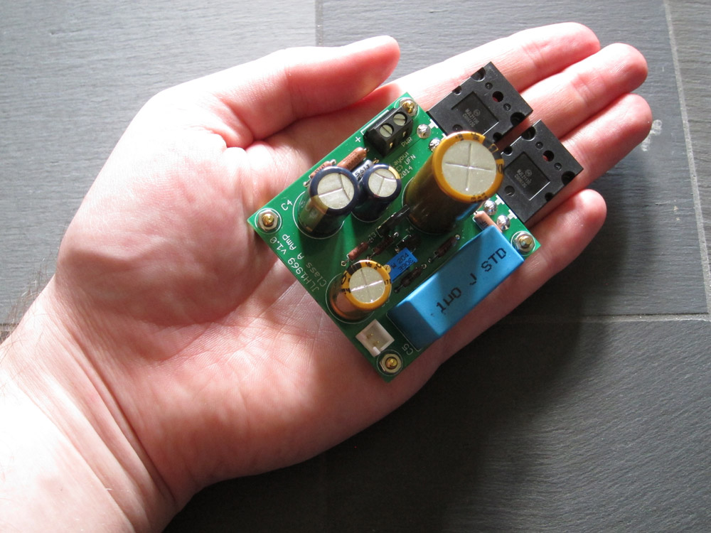
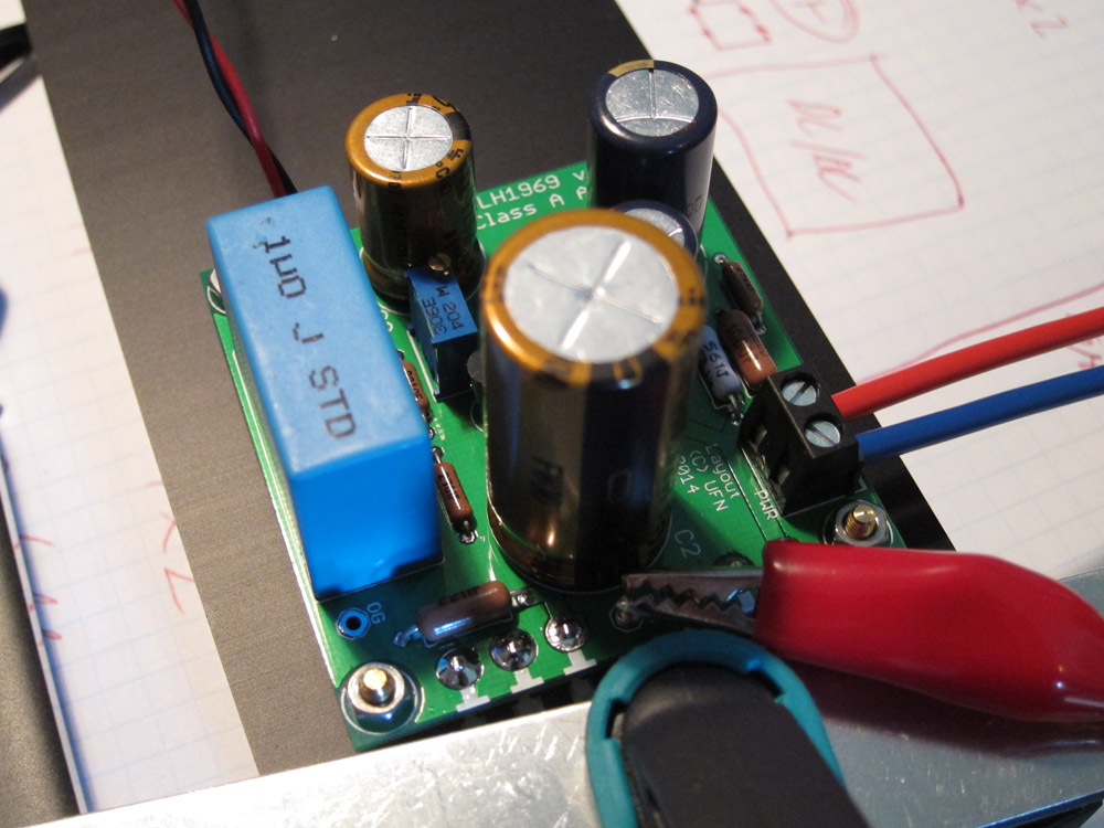
and on the bench for testing 😀
/U.
I haven't done any extensive tests yet, but it plays music so at least that's a good start. Board is 57*58mm and the output devices are MJL21196.
and on the bench for testing 😀
/U.
- Home
- Amplifiers
- Solid State
- JLH 10 Watt class A amplifier