p.s. If you happen to have simulations showing the difference in change of currents of the two o/p transistors I think it will tell an interesting story for those who are new the circuit.
This is of course correct, class A supply current deviations are smaller and smoother than that of class AB or B.
Yes, if you connected the load against +Vs and not against ground, in my previous image, you would get a constant current drawn from the power supply.
Yes, if you connected the load against +Vs and not against ground, in my previous image, you would get a constant current drawn from the power supply.
Very correct................ class A supply current deviations are ............... smoother than that of class AB or B...................
Mikelm's ClassA current theorys are completely wrong.
Believe your simulations.
Rail currents in ClassA amplifiers varies a lot.
With a tiny proportion of ClassA amplifiers that break that almost universal rule.
... could attempt a class A design with some kind of a CCS in the "upper" o/p transistor position - which in theory could draw a reasonably constant current from the PSU regardless of signal ? ? ?
Doing like this, does make final sound better, all my more than dozen recent designs were done with constant currents from all PSUs. At output stage with CCS, load is connected in parallel to the active device. Preliminary stages are used with shunt PS.
An outcome from such approach is big - comparable to transition from B to pure A class. PS circuitry participation in the signal chains is the last what audiuophile would like to have in his system.
Interesting to hear your experiences Vladimirk. Although I do not like using an o/p cap I do think the o/p stage you describe is very elegant - one step on from JLH 1969 version. Would like to see your cct if you are happy to post it.
mike
Interesting to hear your experiences Vladimirk. Although I do not like using an o/p cap I do think the o/p stage you describe is very elegant - one step on from JLH 1969 version. Would like to see your cct if you are happy to post it.
mike
Hello, Mike
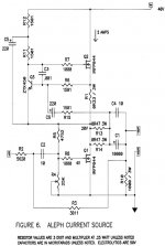
First I would like to mention, that one could achieve a wide spread of the ratios output/rail currents within class A topologies. A bright example of this - modulated Alef current source, proposed by Nelson Pass. Without modulation - we have situation of no signal current through the rail. By increasing the degree of modulation we move to more and more signal current through the rail. At this, efficiency is increasing, but sound quality is compromised (subjectively, since no spectra prove it). I guess, at JLH 1969 one also can adjust operation of the output stage, in order to vary the output/rail currents ratio.
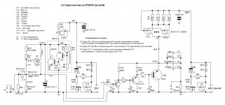
As for my personal preferences, after dozens of designs I stay with this topology nowadays (excuse for non-english notions, I could re-draw it if interesting). Output stage is made with VHF power bipolar transistors (300W transistor at the output). This schematics works with PMC EB1i speakers (3,5 Ohms impedance), therefore standing current is high. Power supply is in external cabinet, amp itself is big and heavy.
Also I would like to add, that caps participate in the signal chain in any case, absence of o/p caps leads a person to false conclusion, that sound comes from schematics itself. No-no, the same measures must be applied to the rail caps, absolutely similarly as to o/p caps.
Attachments
Last edited:
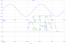
There is one exception, when the current supplied by PSU to class A SE amplifier is almost constant. Please see the attached image. Bottom Darlington is a CCS, MOSFET is an amplifying device and load is connected to +Vs (not to GND). Then, a sum of load signal current + MOSFET current is almost constant and equals to the CCS current.
Attachments
There is at least one other exception.
The F5x (and some of the F5t), a balanced ClassA design, is also constant rail current until the amplifier transitions from ClassA to ClassAB.
This "balanced ClassA" exception applies to all such topologies. They are very uncommon.
The F5x (and some of the F5t), a balanced ClassA design, is also constant rail current until the amplifier transitions from ClassA to ClassAB.
This "balanced ClassA" exception applies to all such topologies. They are very uncommon.
Member
Joined 2009
Paid Member
As for my personal preferences, after dozens of designs I stay with this topology nowadays ....
This deserves a separate thread - would love to hear your reasons for choosing the various design elements and parts (PM me instead if you prefer).
Thx
Gareth
There is at least one other exception.
The F5x (and some of the F5t), a balanced ClassA design, is also constant rail current until the amplifier transitions from ClassA to ClassAB.
This "balanced ClassA" exception applies to all such topologies. They are very uncommon.
I would mention, last years industry produces more and more amps, with all speaker terminals being isolated from the ground. This means, they are either balanced, or circlotron. Especially good estimates are given to Vitus Audio amps.
NO !!!!
Very few power amplifiers are of balanced topology.
For constant Rail Currents there is the additional requirement that the balanced amplifiers remain in ClassA.
What proportion of the world population of amplifiers are balanced ClassA
Very few power amplifiers are of balanced topology.
For constant Rail Currents there is the additional requirement that the balanced amplifiers remain in ClassA.
What proportion of the world population of amplifiers are balanced ClassA
Last edited:
This deserves a separate thread - would love to hear your reasons for choosing the various design elements and parts (PM me instead if you prefer).
Thx
Gareth
Gareth, I think I'll open a new thread about this amp. Some time ago I intended to do this, but what has stopped me - special russian transistors were used, so difficult to discuss with diy members. But, now I know, that good substitutes from Motorola are available. VHF power bjts are good due to the low base region resistance and interelectrode capacitances. In spite that one has to use some external resistors and caps, in order to prevent self-oscillations, these external parts are not voltage dependent and are linear. Final sound is felt like more effortless, more "big", more articulated. Especially difference is heared compared to MOSFET output stages. The bandwidth, as in all my amps, is in MHz range. Total value of output caps exceeds 0,1F. Low value of the input (greed-leak) resistor - for allowing bigger input currents, this decreases possible effects of electro-magnetic interactions and effects of wire insulation, effects of imperfect connector contacs. I would use even lower value of the volume pot (3...5kOhms) if would available.
Last edited:
Yes - please begin a new thread ASAP 🙂
I have some questions and guess it would be best to ask them there rather than here.
I have some questions and guess it would be best to ask them there rather than here.
Yes - please begin a new thread ASAP 🙂
I have some questions and guess it would be best to ask them there rather than here.
I have started the new thread - Rails Decoupled SE Amplifier
Hi diyers, I have experimented with linsleys-hoods darlington modification(i.e replacing T1 with a pwr darlington mj3001), but i found that to stabilise it you need to add jlh's stabilisation caps that is 1n from tr3 collector to tr4 emitter,a 100ohm 1n series from tr4 collector to gnd and of course a zobel network. btw,distortion is now supposed to be around .01% at 10w! hope someone can simulate this. thanks
Can you please explain it bit more. I mean is it a direct replacement? I have some original Philips BDX63B. Can I use it as a direct replacement. what all modifications should I do in JLH1969 circuit.
I just went 20 pages back to see if there were any recent recommendations on kits. Here are some of the PCBs
MKHunt using the silliconray ones

Rixsta using JLH 1969 Mini Amplifier by "La Mer"

Probably too low power ...
Ebay #1

Ebay #2

Ebay #3

Which one would you recommend and why?
Thanks,
Jeff
MKHunt using the silliconray ones
Rixsta using JLH 1969 Mini Amplifier by "La Mer"
Probably too low power ...
Ebay #1
Ebay #2
Ebay #3
Which one would you recommend and why?
Thanks,
Jeff
Last edited:
Honestly I would avoid the 69 design. It's simple but it just doesn't perform very well. I have a silicon ray version I am working currently using an SMPS.
I have built the 69 and later versions, prefer the 69 with dual rails. A great sounding amp one day will build the Gem.
Regards
Regards
Honestly I would avoid the 69 design. It's simple but it just doesn't perform very well. I have a silicon ray version I am working currently using an SMPS.
What rail voltage, bias and devices did you use?
PMA seems quite taken with the original and has some nice testing to back it up. Hugh likes it too!

Member
Joined 2009
Paid Member
Which one would you recommend and why?
Thanks,
Jeff
The item with the TO-3 transistors nicely bolted to a metal plate looks nice to me. Why ? - if they come ready mounted that will save you some work. Also the TO-3 packages make for good thermal contact with heatsinks and they have that retro-look.
Thje original '69 is the famous version, you'd be second guessing yourself if you build something different without first building this one.
I don't think single rail is an issue but be prepared to upgrade the output capacitor for best quality.
- Home
- Amplifiers
- Solid State
- JLH 10 Watt class A amplifier