Eric,
my partner at ZUS Audio Inc done just that using two Meanwell smps. The two clock frequencies where not the same by only a few kHz.
When he made some measurements with his picoscope he found that the two clocks cause a number of mixed frequencies all around 80kHz all the way down to 20 kHz. Although he claimed it was not audible you do not know what is present across the tweeter.
Thing is what you might not hear may still be presented to your tweeter.
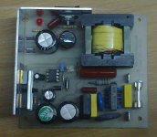
I have in the meantime made him a very simple half bridge +25 - 0 - -25V @ 5 A smps that works fine provided that the zobel networks are properly chosen to critically damp the switching pulse overshoot thereby reducing the HF noise.
The supply is unregulated but a class A amp presents a constant current load and it worked well.
The SMPS is an adaptation of TI's apnote.
my partner at ZUS Audio Inc done just that using two Meanwell smps. The two clock frequencies where not the same by only a few kHz.
When he made some measurements with his picoscope he found that the two clocks cause a number of mixed frequencies all around 80kHz all the way down to 20 kHz. Although he claimed it was not audible you do not know what is present across the tweeter.
Thing is what you might not hear may still be presented to your tweeter.
I have in the meantime made him a very simple half bridge +25 - 0 - -25V @ 5 A smps that works fine provided that the zobel networks are properly chosen to critically damp the switching pulse overshoot thereby reducing the HF noise.
The supply is unregulated but a class A amp presents a constant current load and it worked well.
The SMPS is an adaptation of TI's apnote.
Attachments
Last edited:
I do not have the schematic or layout at home but can post it tomorrow from work if you are interested. Winding the transformer is no problem either and the core is a common core and bobbin that is available all over.
No.............. a class A amp presents a constant current load .........
Most ClassA amplifiers do NOT draw constant current from the supply rails.
AndrewT,
My JLH is constant current, I just measured. So is my two single ended amplifiers. JLH is running 27 VDC at 3.1 Amp cold and 3.2 Amp when the heat sink stabilised at (both amps off the same supply).
My JLH is constant current, I just measured. So is my two single ended amplifiers. JLH is running 27 VDC at 3.1 Amp cold and 3.2 Amp when the heat sink stabilised at (both amps off the same supply).
I can personally tell you to avoid using 2 meanwell smps to power an amp. I tried it and they started oscillating. There may be some way to deal with that but I just gave up. If you want to try an smps take a look at connexelectronics.
Andrew you are right not all class A behaves like this. You can see the current changing if you put a shunt in series with the amp and look at the volt-drop with a scope. A meter averages the current and you see a constant current load. But the change in current is not as drastic as one would expect. From the signal passing through zero to maximum (10V) the current changes by 450 mA but not as much as one would expect. This is true for JLH. However, the single ended class A with CCS remains constant as the current is shared between the speaker and the active element while the current source holds stable.No.
Most ClassA amplifiers do NOT draw constant current from the supply rails.
Last edited:
Hi,
I did not buy Meanwell, the two I bought are double insulated SMPS. Once the amp is completed I will report back. I hope there is no oscillation. This is what I bought ;
SMSL 1438T 14V3 8A Power Adapter FOR TA2020 TA2021 Amplifier LCD Laptop | eBay
Best regards,
Eric
I did not buy Meanwell, the two I bought are double insulated SMPS. Once the amp is completed I will report back. I hope there is no oscillation. This is what I bought ;
SMSL 1438T 14V3 8A Power Adapter FOR TA2020 TA2021 Amplifier LCD Laptop | eBay
Best regards,
Eric
Nico, your analysis is wrong.
Very few ClassA topologies draw constant current.
The very few that do draw constant current are rarely implemented.
That leaves the vast majority of ClassA amplifiers do not draw constant current.
The F5x is a constant current ClassA amplifier up to nearly the ClassA current limit.
A single ended, CCS loaded, single polarity, ClassA amplifier that has the Load returned to the supply rail instead of to the ground rail is also constant current ClassA up to the ClassA current limit.
AndrewT,
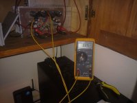
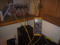
Kindly explain this phenomenon: Music is playing (I cannot prove it though) - this is a JLH from 1969 (what is being discussed here). It is driven by a Meanwel SMPS, the ripple voltage is less than 10mV. The measurement is of supply current shown is both Amp DC and Amp AC. If the supply current was not constant it should register on AC but it does not. However, a constant DC current is present. My statement supporting your view above was incorrect, what I saw on the scope was hash.
Kindly explain this phenomenon: Music is playing (I cannot prove it though) - this is a JLH from 1969 (what is being discussed here). It is driven by a Meanwel SMPS, the ripple voltage is less than 10mV. The measurement is of supply current shown is both Amp DC and Amp AC. If the supply current was not constant it should register on AC but it does not. However, a constant DC current is present. My statement supporting your view above was incorrect, what I saw on the scope was hash.
Attachments
Last edited:
go back to your scope and measure the voltage variations on the supply rails.
That voltage variation is due to the supply tail current times the supply impedance, causing a voltage drop.
That voltage drop (the variation from the maximum at zero output current) is there because the current is varying.
That voltage variation is due to the supply tail current times the supply impedance, causing a voltage drop.
That voltage drop (the variation from the maximum at zero output current) is there because the current is varying.
go back to your scope and measure the voltage variations on the supply rails.
That voltage variation is due to the supply tail current times the supply impedance, causing a voltage drop.
That voltage drop (the variation from the maximum at zero output current) is there because the current is varying.
Sorry I cocked up scope measurement was hash I forgot that it was not a floating ground.🙂
The only class A that I think may follow your suggestion is an over biased class B like the KRELL and only when it exceeds its fixed bias current.
Straw man
Let me draw a straw man - a properly balanced pushpull amplifier (like all the current Class D but in A). Looks like a capital H schematically, with the load as the horizontal stroke.
If you have standing currents I in each arm and balanced, differential drive you theoretically see no current variation in the power supply as long as remain in class A.
How do you get a rail current variation with this architecture?
[Meanwhile, back in the real world an imbalance of 5% is considered acceptable.]
The Rail currents vary with the Output current.
It does this for Push Pull and Single Ended.
Let me draw a straw man - a properly balanced pushpull amplifier (like all the current Class D but in A). Looks like a capital H schematically, with the load as the horizontal stroke.
If you have standing currents I in each arm and balanced, differential drive you theoretically see no current variation in the power supply as long as remain in class A.
How do you get a rail current variation with this architecture?
[Meanwhile, back in the real world an imbalance of 5% is considered acceptable.]
Let's not take your strawman and instead take a Single Ended Amplifier with a CCS load.
The top device is connected from +ve supply rail to the load via a DC blocking capacitor and the CCS device that goes to zero volts.
You set up the biasing to allow the load junction to sit at ~ half supply voltage. The DC blocking capacitor also has ~ half the supply voltage across it.
The quiescent current flows from Supply to Zero Volts.
The Output Bias Current flows through the top device and then on through the CCS device. None goes through the load. The DC blocking capacitor ensures this is so.
Now apply a sinewave to the input.
Allow the sinewave to move to the crest and instantaneously measure ALL the voltages around the circuit and the load.
The Load will be passing Ipk due to Vpk being applied across Rload.
The CCS will still be passing the set Output Bias Current.
The Load Current has to come from the +ve supply rail.
The upper device is at that instantaneous moment passing both the Load current AND the CCS bias current.
The supply rail current = CCS current PLUS Output Current.
Allow the sinewave to return to zero signal voltage.
Now measure all the circuit voltages.
You will find they have returned to the quiescent state.
The supply rail current = CCS current.
Now let's continue with the sinewave signal and let it go down to the -ve crest and measure all the circuit voltages.
The voltage at the load is now reduced to very close to the zero volts. The load now has a net -ve voltage across it, Vpknegative.
The DC blocking capacitor is discharged into the CCS. This is because the Capacitor a quarter of a cycle ago sat with half supply voltage across it and now that capacitor has been dragged down to nearly zero volts. It has to discharge. This is the load seeing a negative current flow, i.e. the pre-requisite for AC signal.
The supply rail is still supplying current but the equation now is
The supply rail current = CCS current MINUS Output Current.
From the two extremes above the supply rail current has changed by an amount
equal to TWICE the load current.
i.e. the supply rail current = bias current +- load current.
That is very much NOT CONSTANT CURRENT !!!!!!!!
Last edited:
I and other Members and text books all describe the AC current in the load of a single ended amplifier in a similar fashion. It has all been posted on this Forum before.
Why do we still have doubters here that refuse to read the literature?
Why do we still have doubters here that refuse to read the literature?
I used two Laptop SMPS (19vdc, 3.5A?) that had separate floating grounds to make a +/- 19vdc supply for a Bobo-zen amp (a stripped down F5).
Worked great, although I did not check for HF Oscillation due to different switching frequencies...
Worked great, although I did not check for HF Oscillation due to different switching frequencies...
Let's not take your strawman and instead take a Single Ended Amplifier with a CCS load.
The top device is connected from +ve supply rail to the load via a DC blocking capacitor and the CCS device that goes to zero volts.
Well, if you deliberately design your output stage to run the signal current loop via the power supply then you'll get an amplifier which varies the power supply current as a function of signal
If you connect your load to +ve supply instead of gnd then no signal current flows through the power supply.
So, back to point A - you can design a Class A amp to either run signal current via the power supply (or not) - even though the nominal DC (AM demodulated) power supply current remains constant.
I think that was the point you were trying to make. Is that correct?
and the same analysis applies to a push pull ClassA output stage.
The rail currents follow the output current. The difference between the +ve rail current and the -ve rail current equals the output current.
And it even applies to a ClassAB output stage where the same definition applies:The rail currents follow the output current. The difference between the +ve rail current and the -ve rail current equals the output current.
The point I made in post2864:
The few exceptions are so rare that in general they can be ignored.Most ClassA amplifiers do NOT draw constant current from the supply rails.
Last edited:
I've been simulating the JLH '69. I wanted to experiment with some low power versions as a small guitar amp and as an intro to amp design which I'm very new to and was hoping someone could help me answer a few questions.
1) In the original Wireless World article there is a high-impedance input modification (Fig. 8) using a FET buffer. Would that be adequate for plugging an electric guitar into and driving the amp?
2) I know nobody goes Class A for power efficiency - but is there any advice on reducing the amount of current this circuit draws for a given supply voltage? Even just some pointers to experiment with?
3) Can I get some help with calculating the output wattage for various power supply configurations - I'm getting:
+/-2V PP on a 5V supply (I calculated 0.5W)
+/-3V PP on a 9V supply (I calculated 1.5W)
+/-6V PP on a 15V supply (I calculated 4.5W)
- that's all into a 4R speaker
Thanks in advance,
- J
The FET input stage still only has around 470k inout impedance. If want higher then you can alter the 680k and 1.5meg, raising them by the same ratio. I think it should be OK "as is" though.
In the original article, altering (raising) R1 and R2 will lower the quiescent current.
To arrive at some values for these resistors we need to know your actual supply voltage. You could for example run the amp on 20 volts and set a low current knowing that power output would be limited (by your chosen current) or you could say you need it to run on 12 volts at whatever current is best for max output into 4 ohms.
- Home
- Amplifiers
- Solid State
- JLH 10 Watt class A amplifier