So JHL is the Chinese guy selling JLH kits?Commonly referred to on this Forum as JLH.

Hi all, I build jhl class a with 4x MJ15003
You guys are so serious !

I don't like the amplifier.
There is not much to like or dislike about the amplifier, it is just a classic design that has been around for +50 years and is still built by enthusiasts every day - I wonder how many have been built since it was published in Wireless World. gannaji I bet you cannot look this up in Wikipedia 🙂
Last edited:
Member
Joined 2009
Paid Member
Thank Bigun, my heatsink is 0.6311 deg C/ W without fan, alumium 150x300x4mm dimension if is OK? anybody have some experience???
Looks OK to me - try it, worse case you learn and modify.
There is not much to like or dislike about the amplifier, it is just a classic design that has been around for +50 years and is still built by enthusiasts every day - I wonder how many have been built since it was published in Wireless World. gannaji I bet you cannot look this up in Wikipedia 🙂
I can definitely say that I built one. 😀
http://www.diyaudio.com/forums/solid-state/3075-jlh-10-watt-class-amplifier-187.html#post2469219
I don't like the amplifier.
Don't worry... the amplifier doesn't like you either.....

Hi Guys,
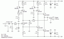
New to this thread. I recently bought the Siliconray (JLH 2005) +- 22Vdc bipolar version but then realized thanks to this forum that the version is way too powerful for my need and heat dissipation..🙂, I then decided to adapt these free PCB for a less powerful version..i.e 9Wrms using +-12Vdc supply with an Iq of 1.5A, see schematics.
Can a good Samaritan have a look at my schematics and confirm if it all makes sense.
I intend to use a switching mode supply.
Thanks a lot.
Eric
Attachments
Last edited:
Hopefully a switching power supply with +- rails. I have seen cases where using two commercial switching supplies cause interference when their frequencies are not absolutely the same - just a warning.
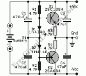
Otherwise use a single 24V supply and create a virtual ground using two transistors, a diode and two resistors.
Otherwise use a single 24V supply and create a virtual ground using two transistors, a diode and two resistors.
Hi Nico,
Can you sketch a quick diagram of that virtual ground circuit. I would love to see how that is done.
Blessings, Terry
Can you sketch a quick diagram of that virtual ground circuit. I would love to see how that is done.
Blessings, Terry
Hi Nico,
No, it's not a +- power supply. I bought 2 power supply each rated 14Vdc, 4A which have their output floating and no ground pin on the AC side. I will simply create a center tap with both outputs since these are totally independant supply.
Rgds,
Eric
No, it's not a +- power supply. I bought 2 power supply each rated 14Vdc, 4A which have their output floating and no ground pin on the AC side. I will simply create a center tap with both outputs since these are totally independant supply.
Rgds,
Eric
That is the one. I have seen others that uses LM317/337 regulators maybe if you search for virtual earth on DIY audio. But the one above has worked for me for many years in all types of amplifier configs.Like this one, of course with the proper voltage ratings for the transistors and capacitors (same idea used in the later Quad power amps).
- Home
- Amplifiers
- Solid State
- JLH 10 Watt class A amplifier


