I bought a couple of those Ebay JLH boards thinking it would be fun little project to play with. Now I see that some guys go all out with this amp. Are they that good sounding?
I wanted to try using a 25V server power supply with it. Its way over-kill being 47A output but I thought it would be interesting. Any benefit to using different outputs than the 2N3055?
Thanks,, Terry
I wanted to try using a 25V server power supply with it. Its way over-kill being 47A output but I thought it would be interesting. Any benefit to using different outputs than the 2N3055?
Thanks,, Terry
Hi Terry,
Unlke amps with push pull follower outputs, this design, depending a bit on the version you have built, can only deliver 2 x the output stage standing current to the speakers so having a supply that can deliver 47A does not bring any advantage to it's operation - although it may not do any harm either.
I would suggest that it would be more advantagous for sound quality to have very well filtered supply.
This design has been very highly regarded since it was first published 44 years ago, having a sound character more like a tube amplifier. I would suggest a standing current of at least 2 amps in the output stages to enable the amp to give reasonably well controlled bass.
Many have reported benefits from adopting more advanced, modern output devices but you may find that some compensation measures will be needed if you use very fast devices.
hope this helps
mike
Thanks Mike,
I know it's way more amps than needed but I have been dying to try this out. On my scope the PS looks very clean almost to the very top of the scopes range, I don see any noise at all until the last three frequencies on the dial and I have to have the sensitivity all the way to see that. Now that I've done this I am going to test some of my other PS to see how they measure up.
I have ordered the 2N3055's. If they are the better way to go I will just stick with them. I have most of the On Semi output devices so I will keep reading and see what folks think.
Thanks again, Terry
I replaced the output devices on my ebay kits with MJ15003s, partly because I had them, partly because they are supposed to sound better and partly because the supplied 2N3055s looked a bit questionable in origin. Since I haven't tried 2N3055s first I don't know what difference it will actually make, but the last point alone makes it worthwhile for me - I don't really want to have to take the whole thing apart to replace a pair of blown transistors.
/U.
/U.
I may try both while I have it in breadboard stage and see if I can hear or see any difference. I might even try some plastics. I don't know how to add in a compensation circuit so I may not.
How big a sink are you using? If the power supply works well, I may use a tunnel with a fan since the PS needs some cooling anyway.
How big a sink are you using? If the power supply works well, I may use a tunnel with a fan since the PS needs some cooling anyway.
I started with 2n3055 then changed to mj15003. Sound much better. I set my current at a low 1.2A but I still use active cooling with a silent computer fan on the heat sink. Heat sink is not too big so active cooling is the only option. Without fan, the heat sink is too hot to touch. I have posted my pictures, you can search my posting.
I'll just go ahead and use the 15003's from the start. I should have asked before I ordered parts. I probably have 40 15003's left over from my Krell clone building. If these don't need compensation then it is a no brainer.
I saw you heat sinks, I will go a lot bigger than that. I would like to not use a fan.
Thanks, Terry
I saw you heat sinks, I will go a lot bigger than that. I would like to not use a fan.
Thanks, Terry
OK, I have them burning. The only issue right now is that when they first fire up, with the input shorted, running on +24.5V rail I see about 6Vdc on the output. It starts dropping and finally after about two minutes, it will drop to about 80mv on one side and 5-10mv on the other. I haven't tried hooking up dummy load to it yet to see if that will have an affect on that.
Is this typical for the JLH?
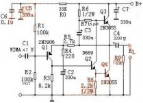
Also, the schematic above shows am R9 resistor that is 10K. My board doesn't have that part. Would adding it be an improvement? The other JLH schematics I have looked at don't have it either.
Thanks, Terry
Is this typical for the JLH?
Also, the schematic above shows am R9 resistor that is 10K. My board doesn't have that part. Would adding it be an improvement? The other JLH schematics I have looked at don't have it either.
Thanks, Terry
Output protection capacitors need charging
Terry, R9 and/or the speakers have to charge up the output capacitor at turn on. If you have no R9 and no load the capacitor will only charge up via leakage.
In the real world I get more thump from my power supply than the speakers at turn on.
Terry, R9 and/or the speakers have to charge up the output capacitor at turn on. If you have no R9 and no load the capacitor will only charge up via leakage.
In the real world I get more thump from my power supply than the speakers at turn on.
This is normal for all Single polarity power supply amplifiers.
Use a speaker isolation relay to protect the speaker.
The relay needs a resistor on the NC contact to allow the output capacitor to charge up.
Simply disconnecting the speaker before power ON, is not good enough.
BTW the pulse is half the supply voltage. The current pulse gets bigger if you increase the capacitor to pass lower frequencies.
Andrew,
Both your PM box and email inbox are full; I'm about to leave home for a week, but I have a message for you. Can you please make a bit of room for a PM/email?
Ciao,
Hugh
Both your PM box and email inbox are full; I'm about to leave home for a week, but I have a message for you. Can you please make a bit of room for a PM/email?
Ciao,
Hugh
Thanks Guys,
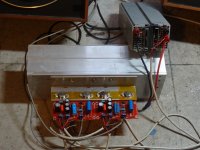
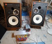
You were right. As soon as I hooked up the speakers, it settles very quickly. Both sides go to 1mv within a couple seconds. Slight turn-on thump but nothing exciting. Best of all, It Is Playing Music
How's this for a little DIY action.
You were right. As soon as I hooked up the speakers, it settles very quickly. Both sides go to 1mv within a couple seconds. Slight turn-on thump but nothing exciting. Best of all, It Is Playing Music
How's this for a little DIY action.
Attachments
I noticed a little weirdness today with this amp so I checked the input and I am seeing about 3VDC across the inputs. What could be causing this?
Thanks, Terry
Thanks, Terry
Input capacitor
Hi. Just pondering the input capacitor. I found posts in this thread dealing with different types of input caps, but I couldn't find one that suggested no input capacitor. Do I really want to spend more on the input cap than I did on the complete amplifier? I am building the higher power version published by Geoff on the Class-A Amplifier Site. Am I able to get away without an input cap if my previous stage has less than 5mV DC offset (transistor preamp) or has an output capacitor (tube preamp)?
Hi. Just pondering the input capacitor. I found posts in this thread dealing with different types of input caps, but I couldn't find one that suggested no input capacitor. Do I really want to spend more on the input cap than I did on the complete amplifier? I am building the higher power version published by Geoff on the Class-A Amplifier Site. Am I able to get away without an input cap if my previous stage has less than 5mV DC offset (transistor preamp) or has an output capacitor (tube preamp)?
I was wondering about that. It calls for a WIMA 4.7uf. I had some large 4.7 uf film caps so I used those. Is there something special about WIMA that I should have ued them instead?leaking capacitor?
Hi. Just pondering the input capacitor. I found posts in this thread dealing with different types of input caps, but I couldn't find one that suggested no input capacitor. Do I really want to spend more on the input cap than I did on the complete amplifier? I am building the higher power version published by Geoff on the Class-A Amplifier Site. Am I able to get away without an input cap if my previous stage has less than 5mV DC offset (transistor preamp) or has an output capacitor (tube preamp)?
Would have to see the circuit. If its an LTP input then the cap is probably still needed to allow equal DC bias currents (and so allow for minimum offset).
I was wondering about that. It calls for a WIMA 4.7uf. I had some large 4.7 uf film caps so I used those. Is there something special about WIMA that I should have ued them instead?
The circuit in post #2809 will have measurable "DC" on the input because the cap is floating. Tie it via a 470K to ground and no cap of any variety should show measurable DC on the input.
Would have to see the circuit. If its an LTP input then the cap is probably still needed to allow equal DC bias currents (and so allow for minimum offset).
The circuit in post #2809 will have measurable "DC" on the input because the cap is floating. Tie it via a 470K to ground and no cap of any variety should show measurable DC on the input.
Where would I connect the 470K, at the input side or the side away from the input?
It may be oscillating - this would be my best guess
I didn't see anything on my scope. How would I look for that?
Thanks, Terry
- Home
- Amplifiers
- Solid State
- JLH 10 Watt class A amplifier