To test the heat sink all you need to know is the temperature rise at one watt. So if you bolt a 10 watt 1 ohm resistor to it and flow a constant 1 amp through it you measure the heat sink temperature before you start heating it and say half hour after, then subtract beginning temperature from end temperature and get degree centigrade rise/watt of power. Multiply this by 180 watt and add the ambient temperature to see if you can cook on it.
Sorry Nico, but your method has ignored the Delta Temp (Ts-Ta) effect.
A correction must be applied to convert to different Delta T.
eg. A heatsink that measures 1C/W when Delta T=70C degrees could be around 1.4C/W when measured @ Delta T ~30C degrees. That would be a De-rating Factor of 1.4 and maybe DF=1.5 @ 20Cdegrees.
A correction must be applied to convert to different Delta T.
eg. A heatsink that measures 1C/W when Delta T=70C degrees could be around 1.4C/W when measured @ Delta T ~30C degrees. That would be a De-rating Factor of 1.4 and maybe DF=1.5 @ 20Cdegrees.
You could also just bolt a 2N3055 to the heatsink and set the current with an emitter resistor and suitable base voltage etc. (including any cmpensation or using another transistor to limit the current). As long as you kept the collector volts to something low (<40) you could dissipate tens of watts and check the heatsink temperature. Just measure the volts across it (Vce) and Ic (and if you want to include the base power add that too) to check the power.
I don't think the thermal mass is important for a class A amp. YOu just need the thermal resistance to know how hot it will get. Keep measuring the temperature until it stabilises and you will have an idea of the thermal mass anyway.
John
I don't think the thermal mass is important for a class A amp. YOu just need the thermal resistance to know how hot it will get. Keep measuring the temperature until it stabilises and you will have an idea of the thermal mass anyway.
John
You could also just bolt a 2N3055 to the heatsink and set the current with an emitter resistor and suitable base voltage etc. (including any cmpensation or using another transistor to limit the current). As long as you kept the collector volts to something low (<40) you could dissipate tens of watts and check the heatsink temperature. Just measure the volts across it (Vce) and Ic (and if you want to include the base power add that too) to check the power.
I don't think the thermal mass is important for a class A amp. YOu just need the thermal resistance to know how hot it will get. Keep measuring the temperature until it stabilises and you will have an idea of the thermal mass anyway.
John
Thank you very much. I think i wil try this method and the method with the resistors.
Physics ain't just an idea
Andrew, where did you find out about this? It's new to me - and doesn't align with Fourier's law
nor the (small) increase in radiated heat
Sorry Nico, but your method has ignored the Delta Temp (Ts-Ta) effect.
A correction must be applied to convert to different Delta T.
eg. A heatsink that measures 1C/W when Delta T=70C degrees could be around 1.4C/W when measured @ Delta T ~30C degrees. That would be a De-rating Factor of 1.4 and maybe DF=1.5 @ 20Cdegrees.
Andrew, where did you find out about this? It's new to me - and doesn't align with Fourier's law
nor the (small) increase in radiated heat
Andrew, where did you find out about this? It's new to me - and doesn't align with Fourier's law
nor the (small) increase in radiated heat
Check this - Thermal Performance and Temperature Rise Above Ambient
Please note that the thermal performance at different temperature rises, varies from heatsink to heatsink and that the correction factor K is useful as an approximate guide only.
The best is (as you have already been told) to use a transistor on a heatsink and give it the same power as you expext to use with your amp.
A small resistor on a big heatsink is not a very good idea. It is not that simple. Temp rise (as everything else on the world i suppose) is not linear. Anyway, TEST it yourself and see what happens. Then tell us 🙂
An externally hosted image should be here but it was not working when we last tested it.
A small resistor on a big heatsink is not a very good idea. It is not that simple. Temp rise (as everything else on the world i suppose) is not linear. Anyway, TEST it yourself and see what happens. Then tell us 🙂
Thank you Hoch.
Most good heatsink manufacturers give this data.
Especially for cooling with natural convection, the hotter a heatsink becomes, the more effectively it dissipates heat
Thanks - that makes sense. I thought the suggestion was that it got worse not better.
As the difference Ts-Ta goes lower, the heatsink dissipation gets worse.
Almost no one builds an Audio Amplifier where Ts-Ta is around 70 to 80Cdegrees.
Most tick over at deltaT of ~10C and operate at loud SPLs ~20 to 30C
Even big ClassA only get up to ~30 to 35C
Almost no one builds an Audio Amplifier where Ts-Ta is around 70 to 80Cdegrees.
Most tick over at deltaT of ~10C and operate at loud SPLs ~20 to 30C
Even big ClassA only get up to ~30 to 35C
Almost no one builds an Audio Amplifier where Ts-Ta is around 70 to 80Cdegrees.
Can't round here anyhows- Ta can approx 50C ! You're a brave person to design with Ta < 35C and you need some die-to-case delta T too!
Ta is ambient temperature.
It is usually in the range 18° to 35°C.
Ts is the heat sink temperature it is usually high then ambient if you want to dissipate any heat.
The difference Ts-Ta (in Centigrade degrees) determines the heat dissipating ability of the heatsink.
It is usually in the range 18° to 35°C.
Ts is the heat sink temperature it is usually high then ambient if you want to dissipate any heat.
The difference Ts-Ta (in Centigrade degrees) determines the heat dissipating ability of the heatsink.
Not round here! (I'm not in the outer hebrides 😀 ) (O'wise it's all +1 from me)Ta is ambient temperature.
It is usually in the range 18° to 35°C.
When Ta is unusually high it is even more important that DeltaT be designed to be low.
That's where ClassA and very high bias ClassAB become virtually impossible to cool adequately.
That's where ClassA and very high bias ClassAB become virtually impossible to cool adequately.
That's where ClassA and very high bias ClassAB become virtually impossible to cool adequately.
Agreed - I remember the first time I saw a Pass Aleph very clearly.
I've also done a fair bit of liquid cooled electronics. What a pain!
Hello to all colleagues here,
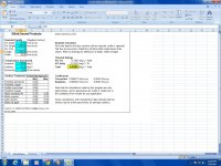
I have found a excel sheet from Rod Eliott that might simulate very close to the real thing (my radiators). Below are the results for one pair of output transistors and the excell sheet. Did anyone tried it before and compare it with a real world radiator that he posessed?
Thanks in advance.
PS: excuse my rought english.
Attachments
You can perform this test for any wattage you please. From the data you can connect the points to create a graphical representation just like a manufacturer would - no guess work, just factual practical data no space science or brain surgery required. You can even do it using the intended transistors and mounting method you will use. What can be easier or more accurate - some spreadsheet?To test the heat sink all you need to know is the temperature rise at one watt. So if you bolt a 10 watt 1 ohm resistor to it and flow a constant 1 amp through it you measure the heat sink temperature before you start heating it and say half hour after, then subtract beginning temperature from end temperature and get degree centigrade rise/watt of power. Multiply this by 180 watt and add the ambient temperature to see if you can cook on it.
Made a little progress on my JLH projects.
1) Ebay 1969 clone boards are now cased up and just awaiting final wiring (well, more or less..)
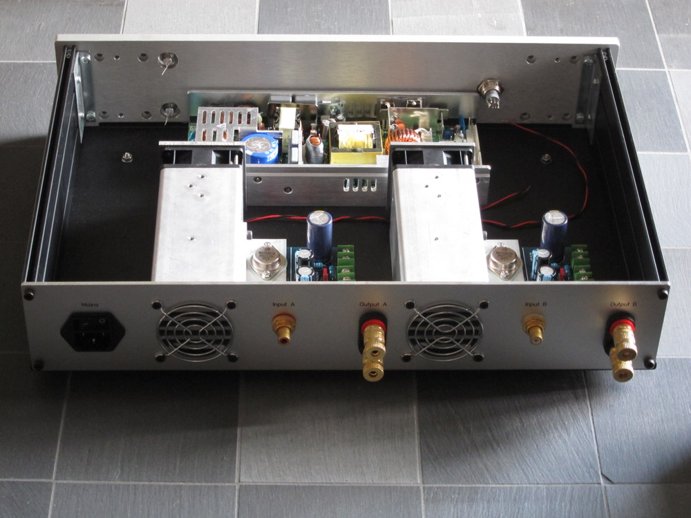
2) My own PCBs for the JLH update circuit are working 😀
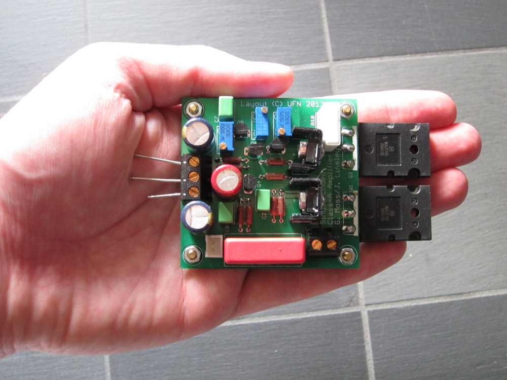
A few more pics in the blog as usual.
/U.
1) Ebay 1969 clone boards are now cased up and just awaiting final wiring (well, more or less..)
2) My own PCBs for the JLH update circuit are working 😀
A few more pics in the blog as usual.
/U.
- Home
- Amplifiers
- Solid State
- JLH 10 Watt class A amplifier