Graham Maynard said:Hi Millward I'm not going to jump through the keypad at you, but it appears that someone called Sloan has suggested 2uF loading.
I am not going to jump at you for failing, again, to understand the context under which Sloan raised the 2uf issue. And to help your reading comprehension also, should I point it to you that Sloan said it was excessive, as I wrote in my post that you had quoted?
Please do all us and yourself a favor next time by understanding what is being discussed here before responding.
Thank you very much.
BTW: good work on your JLH revision. That is one interesting design that needs to be investigated further.
POST 793.
Hi Upupa Epops.
You appear to believe that the JLH output stage is quasicomplementary, and out of date.
Are you also suggesting that is wrong for us to have an interest in improving its performance in whatever way possible, and that we might as well close up shop because we are wasting our time?
20 years ago I heard those symmetrical amps you mention, and they were expensive rubbish compared to the JLH. I used to have to fix them for a 'Hi-Fi' shop when they blew because of loudspeaker reactance, and I was obliged to ignore their colourising characteristics and highly audible current limiter induced shortcomings when compared to valve designs.
Yes of course audio has moved on, but have you actually heard an adequately powered JLH amp being used at normal listening levels, or are you just stating that you have found something that satisfies yourself ?
I have simulated some extremely low distortion and powerful full spec. updated JLH-69 based circuits with circa 50nS of closed nfb loop propagation delay.
These do not impart a sound of their own making, but I still have a completely open mind, so do please give me a link where I can study the 'Accuphase A 20' circuit you recommend.
Please. I do genuinely do want to see it.
I don't believe that I have been wasting my time, but I do need to know.
Cheers ......... Graham.
some not-so-deep thoughts on the JLH
we have seen quite a few modifications on the original jlh: first the mosfet, then tschrama's double-barrel'd mosfet, then graham's still-unnamed modification ("nested" feedback?). they seem to perform better than the original jlh (I know, I know, that's still debatable).
I think there is considerable room for improvement on the original jlh (not to say that it is not a great design to begin with):
1) the original jlh seems to have used small iq for the driver stage, restricting its ability to drive tough loads.
2) there appears to be an advantage to the mosfets as output devices: they remediated the impedance mismatch;
3) mosfet as driver doesn't seem to gain much in performance: i guess their non-linearility and low gain there didn't help.
4) bootstrap vs. constant current source: bootstrap worked surprisingly well, and is very simple to implement, especially in large current situation.
My personal view (highly biased) is that going to dual rail or using complicated biasing mchanisms like in the 1996 design may just spoil the fun on this simplistic design, and doesn't gain much, as evidenced by all the "instability" problems people run into in various versions of the 1996 design.
Graham's design so far represents the largest deviation from the original jlh and probably the single largest improvment in thd and slew rate. I will try to simulate a mosfet version of it and re-wire my amp to see if I can hear anything (highly unlikely given my half-deaf ears, 🙂).
your thoughts?
Hi all,
Graham has 'put the bone in the doghouse' again.. his input arangement (Compound-Feedback-Pair, CFP ?) boosts the openloop gain considerebly, about equal as the second bootstrap in the MOSFET version and simulates as an improvement. His method works with the MOSFET version too, but pahse margin is offcourse reduced. His proposed schematic is interesting indeed! 😎
However I'm in agreement with Geoff that high openloop frequency response coupled with inherent high phase margin might just be a favourable charateristic the amplifier.
My first proposed modifications were also pointed towards higher openloop gain, but now I'm not so sure anymore wheater that's the best strategy.
Regards,
Thijs
tschrama said:However I'm in agreement with Geoff that high openloop frequency response coupled with inherent high phase margin might just be a favourable charateristic the amplifier.
Regards,
Thijs
I agree. so far, the only "concern" I have for graham's version is the narrower open loop response which I think is the result of the feedback and compensation scheme in that verion (the 10k/22pf network has been disabled in my simulation).
the "pleasant" sound in the original jlh might be the result of its simple feedback scheme?
JLH
To X-pro and Graham Maynard : As schoolboy I was learned, that if are in pp amp used in output stage transistors with the same polarity, this amp is called as " quasicomplementary " and basic connection of JLH is thus connected and I belive my school teacher 🙂 . Yes, absolutely most of amps are not good and we can hear their shortages. Yes, if we use " good tuned " class A amp ( and it JLH probably is - after many years of permanent improvement 😉 ), we can hear little bit better (or much better ) sound. But gentlemen, I am an " old steppenwolf ", I was build and heard many amps and I know whatabout I'm talking. Quasicomplementary amps have nonsymetrical SR and output impedance and their frequency compensation is in every time compromis. It all is by realy closely listening hearable, certainly if you have another good amp for comparision. Yes, so called complementary transistors are not realy complementary, but their parameters are much more close ( in look of driver stage ) then quasicomplementary connection. Now I must go away, so please if anybody here have schematic of Acc. A 20, let look guys on it and later we can talk about this " honest amp " ( or about another ) in comparision with JLH 😎 .
To X-pro and Graham Maynard : As schoolboy I was learned, that if are in pp amp used in output stage transistors with the same polarity, this amp is called as " quasicomplementary " and basic connection of JLH is thus connected and I belive my school teacher 🙂 . Yes, absolutely most of amps are not good and we can hear their shortages. Yes, if we use " good tuned " class A amp ( and it JLH probably is - after many years of permanent improvement 😉 ), we can hear little bit better (or much better ) sound. But gentlemen, I am an " old steppenwolf ", I was build and heard many amps and I know whatabout I'm talking. Quasicomplementary amps have nonsymetrical SR and output impedance and their frequency compensation is in every time compromis. It all is by realy closely listening hearable, certainly if you have another good amp for comparision. Yes, so called complementary transistors are not realy complementary, but their parameters are much more close ( in look of driver stage ) then quasicomplementary connection. Now I must go away, so please if anybody here have schematic of Acc. A 20, let look guys on it and later we can talk about this " honest amp " ( or about another ) in comparision with JLH 😎 .
quasicomplementory
it is all in the semantics. and I don't see why we should be arguing about them. the pudding is in the listening where according to some people the jlh excels (in my personal experience it does pretty well vs. some good commercial amps but I am no golden ears).
I think you have a valid point that the jlh (and its various incarnations) may be overhyped because builders put their (biased) view forward. and in terms of performance figures (slew rate and thd for examples) the jlh is no match for some of the amps (a lot of the amps out there actually).
But if you believe in their builders, the jlhs seem to have a case. That's not to say that the JLH is THE amp to beat all.
POST 802.
Yes Millwood, I'm glad to hear that Sloan said 2uF is excessive, and I must admit I did not spot you had written that.
There's much going on here, and in my own life, and I'm working hard to pass on as much as I can to this forum.
My priority was pointing out to you that your continued 2uF testing is not actually proving anything sonically, and I was wanting to get you to question your own, and anyone who suggests it, their real reason for doing it.
It does not matter what value of capacitor is tried; real-world loudspeakers have resistance and inductance in series with any capacitance they might embody. I know that in the past this has been a test to check for stability, and I have wasted much time doing it on my own testbench, but what do the results actually prove ? Simulated cable, crossover and multi-loudspeaker loads should be much more realistic for computer work.
Please allow me to clarify that here in Europe we don't write the longhand value of 2,200uF, we write 2.2mF. (millifarads). Normal European standards ! Likewise we don't normally have some of the resistor values you use in the US.
POST 796.
Tschrama, its not the amplifier's phase angle that is the problem, but the loudspeaker back emf damping control which becomes 90 degree leading ( quadrature ) at low audio frequencies.
Start up your amp with another high value capacitor already across the 2.2mF, say 22mF via a toggle switch. Then play a well defined piece of music and switch the higher value out of and back into circuit.
You should immediately notice the difference in bass loudspeaker cone control.
Some loudspeaker systems behave differently to what their manufacturer intended when they are quadrature damped, i.e. when the amplifier's (capacitor) damping current flow is out of phase with the loudspeaker's terminal voltage.
Does a Mosfet version of my circuit have better slew in both directions ? Is it still stable ?
POST 798.
Millwood. I'm having a right laugh here. Is Mosfet your middle name ?
Can you simulate any better transistors in my modified circuit ? With TIP3055 the open loop bandwidth is about 15kHz, and higher might be possible with more modern plastic drivers.
The 10k + 22pF components shunt limit the gain at about 10MHz. I did not think of it as nested feedback because there is much more of that from the base-collector capacitance within the BD139 itself. The BD139 itself limits the positive slew but keeps the amplifier stable, though such internal capacitance might have been a problem within a conventional VAS driver stage.
I have made dozens of different JLH-69 variant circuits down the years, 100W sliding bias, class-AB, class-B with that same three transistor output arrangement, and others, the odd one of which failed rather dramatically. I stick to bipolars, but one of my class-AB topologies might work with Mosfets, will have to see what I can find and pass on from my archives.
Cheers for now ............ Graham.
Re: JLH
I'm affraid your school teacher was mistaken. And I think the terminology is important. The only circuit which is called quasicomplementary is the one where only one of the transistors (or usually darlingtons) on the output is replaced with a combination of two transistors of opposite polarity. Mind you, just to illustrate that your teacher's definition is wrong, think about a transformer coupled PP output stage using two transistors of the same polarity. There are many more circuits which would fit your teacher's description and definitely can not be called "quasicomplementary" . JLH is one of these 🙂 .
Cheers
x-pro.
Upupa Epops said:To X-pro and Graham Maynard : As schoolboy I was learned, that if are in pp amp used in output stage transistors with the same polarity, this amp is called as " quasicomplementary " and basic connection of JLH is thus connected and I belive my school teacher 🙂 .
I'm affraid your school teacher was mistaken. And I think the terminology is important. The only circuit which is called quasicomplementary is the one where only one of the transistors (or usually darlingtons) on the output is replaced with a combination of two transistors of opposite polarity. Mind you, just to illustrate that your teacher's definition is wrong, think about a transformer coupled PP output stage using two transistors of the same polarity. There are many more circuits which would fit your teacher's description and definitely can not be called "quasicomplementary" . JLH is one of these 🙂 .
Cheers
x-pro.
Graham Maynard said:My priority was pointing out to you that your continued 2uF testing is not actually proving anything sonically, and I was wanting to get you to question your own, and anyone who suggests it, their real reason for doing it.
OK. I got it.
so anyone of us listening to sine waves? no? then let's not to simulate with sine waves and use the stats based on sine waves.
anyone of us listening to square waves? no? let's not to simulate with square waves;
anyone of us using perfect zero resistance superconductors in our circuits? no? let's simulate all wires with resistors.
anyone of us using perfectly matched transistors? no? let's not simulate using exactly the same transistor models.
anyone of us listening to amps in RF free environment? no? let's simulate that as well.
anyoneo f us listening to simulations? no? throw your spice out of the window.
why don't we simulate with real music. why don't we feed our simulation with Britney Spears? no? you don't listen to Britney Spears? Michael Jackson? You listen to the Dixie Chicks? But I don't! so no more real life music.
You got the point? the 2uf is far more from realistic. as a lot of things we do. But it allows you to have a bench mark to see how the amp works driving capacitive load.
If you aren't happy with it, provide your own, and i will find 10 reasons why yours is not realistic, for each and every reason you think the 2uf method isn't.
I just hate those non-constructive conversations. If you think the methodology being used is wrong or insufficient, provide your own.
Graham Maynard said:Millwood. I'm having a right laugh here. Is Mosfet your middle name ?
that's one cheap shot class-less comment.
Graham Maynard said:Can you simulate any better transistors in my modified circuit ? With TIP3055 the open loop bandwidth is about 15kHz, and higher might be possible with more modern plastic drivers.
Cheers for now ............ Graham.
first of all, define "modern" for me. If you can, name a transistor and I will simulate it for you (if I can find it in my simulator).
show me the chart and I will show you mine. BTW, my simulator (protel dxp demo) is freely available over the net so if you aren't happy with my results, go run your own simulation.
I simply hate this kind of conversations.
POST 807.
Hi Upupa Epops.
Is it not the case that early transistor amplifiers with NPN only power transistors were called 'quasicomplementary' because they used a small PNP device to make one of the output halves run as if PNP ?
Surely the JLH-69 and 96 are non-complementary ?
In its original form it was not balanced, but it is possible to run it with a matched balance that is better than can be acheived using complementary devices.
Cheers .............. Graham.
Graham Maynard said:Can you simulate any better transistors in my modified circuit ? With TIP3055 the open loop bandwidth is about 15kHz, and higher might be possible with more modern plastic drivers.
Cheers for now ............ Graham.
here it is, open loop bode plots for your very modified circuit, using mpsa55/mje15030/mje15030x2.
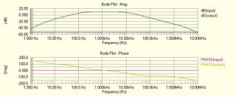
millwood said:
this is a very promising design. I scaled back some of the numbers: mostly caps. I also used different transistors: mpsa55/mje15030/mje15030x2 as I don't have the original transistors in my simulator (2n3055 in protel dxp / ST Microelectronics library doesn't work for some reason).
It performed very well in both closed and open loop tests:
-3db: about 2-3Mhz.
thd: 0.08% @1k, 0.07% @ 10k, 0.07%@20khz.
I am trying to figure out what contributed to the improved performance. so I altered the above circuitry (a watered down version of Graham's JLH1969). here are some new numbers:
if I sever the input / driver feedback, and ground the 680ohm resistor and increase its value to 8.2k as in the original jlh1969, I got the following numbers:
-3db: about 1mhz;
thd: 0.10% 1k, 0.10% @ 10k; 0.22% at 20k.
alternatively, the 680ohm resistor remains in place and we change the feedback resistors from 56/680 to 220/2.7k.
-3db: remains the same.
thd: 0.23% at 1k, 0.24% at 10k, 0.24% at 20k.
so somehow the magic combination of feedback resistors and the feedback between input / driver stages did the trick.
Millwood
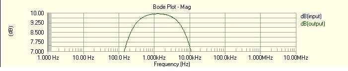
I have been wondering for a while now why all the simulated open-loop bandwidth figures that you have quoted are significantly lower than I, and others, have obtained. For example, you say above that Graham's circuit has an open loop -3dB point of about 10kHz whereas my simulation gives it as 31kHz.
The answer is the model you are using. The MJE15030 gives much lower open-loop bandwidth as you will see from the attached plot. This was generated using a standard JLH1969 circuit and changing only the driver transistor (Tr3). The difference when this is an MJE15030 is clear.
You have posted a multitude of figures recently, all of which are not realistic because of the model you use. This only serves to add confusion to the debate. Before posting any more results, I suggest you obtain some more suitable models. For example, models for the BD139, and appropriate power transistors, are available from the manufacturers' websites.
You have also made deleterious comments directed towards Graham, based on these incorrect figures, for which I think you owe him an apology.
Geoff
Attachments
Geoff said:The answer is the model you are using. The MJE15030 gives much lower open-loop bandwidth as you will see from the attached plot.
so what model did you use for the mje15030? and why are you convinced that mine (from protel dxp) is wrong?
Geoff said:You have also made deleterious comments directed towards Graham, based on these incorrect figures, for which I think you owe him an apology.
Geoff
I don't quite understand you and I stand behind my statements any time of the day. If indeed the model in protel is wrong for the device, I am happy to change it but I need someone to establish for me in a logic way that it is indeed incorrect.
Hi all,
Based on all your comments and some additional suggestions by Geoff I made a simulation-format to fascilate simulation resulst.
It can be viewed at
http://home.tiscali.nl/eurocondit/Dear_DIY.doc
Any suggestions and comments are welcome,
Regards,
Thijs
Based on all your comments and some additional suggestions by Geoff I made a simulation-format to fascilate simulation resulst.
It can be viewed at
http://home.tiscali.nl/eurocondit/Dear_DIY.doc
Any suggestions and comments are welcome,
Regards,
Thijs
- Home
- Amplifiers
- Solid State
- JLH 10 Watt class A amplifier