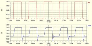

without much analysis (any analysis actually), it seems that the mosfet is considerably faster than the BJT, and can drive capacitive load a lot better.
However, both versions have asymmetric slew rates (more symmetric for the mosfet version tho.). Maybe that's due to the asymmetric nature of the phase splitter / driver?
up slew rate for the bjt is about 2v/us. and the same slew rate fo rthe mosfet is about 4-5v/us.
for comparison purposes, I also put "gate stoppers" in the BJT version (value 0.00001ohm) so I can see the base current on the BJT output devices and compare with that on the MOSFET output devices.
here it is. The MOSFEt version, obiviously, has the initiate upshot and pretty smooth thereafter.
Attachments

also, putting a zobel network on the speaker terminal doesn't cure the overshot, in case you are interested.
for the protel users, the "square" wave is called pulsed wave and you have to play with the parameters to get it to work.
I am thinking about the slower up slew rate. The output device, either bjt or mosfet, would be working as an emitter follower and that should have been the fastest. so everything else being equally, the up slew rate should have been faster. but it isn't.
I suspect that the asymmetric Zout on the phase splitter is to blame. The phase splitter works as a common emitter and has high output impedance.
Since the BJTs are current driven devices vs. MOSFETs as voltage driven devices, the Zinput of those BJTs is much lower than that of the MOSFETs, worsening the Z mismatch.
I think if we increase the Iq on the original JLH may help slew rate a little.
Hi Millwood,
Your findings seem to point to the same directions as my simuations results (qualitative), but differ somewhat in the numbers (quantitative). I try to resist the urge to do more similations untill there is some kind of format/protocol.
Have you tried the proposed MOSFET circuit yet?
G'night .. ehhh early morning ? 🙄
Thijs
Hi All,
A couple more thoughts.
The present design investigations are still being completed using the 30yr old specified 2,200uF series output capacitor.
This value was not high enough, even in 1969, because when I paralleled it with 10,000uF I could hear a distinct improvement in bass response and loudspeaker damping, 2.2mF + 10mF made it equal the valve amplifiers I was using for comparison.
A minimum of 10mF (10,000uF) should be used, and preferably 20 to 22mF when the single power rail version is being constructed.
Testing at full power does not give a proper indication of how clean the amplifier might be whilst running at its normal listening level.
You might have two amplifiers measuring equally at maximum output, say 0.1% distortion, but one which does not have a balanced output stage could still run at 0.1% at 1W, where one that is properly class-A push-pull balanced might acheive 0.01% and sound better as a result.
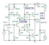
I'm now going to try and attach a slightly modified JLH circuit that Tschrama and Millwood might try to beat with their own four transistor designs. 2N3055s are shown but other types can be tried. Different input transistors could be used like a BC556, but I have not yet ventured beyond the BD139 driver because it not 'too good' and thus does not invoke instability.
Cheers for now ............ Graham.
A couple more thoughts.
The present design investigations are still being completed using the 30yr old specified 2,200uF series output capacitor.
This value was not high enough, even in 1969, because when I paralleled it with 10,000uF I could hear a distinct improvement in bass response and loudspeaker damping, 2.2mF + 10mF made it equal the valve amplifiers I was using for comparison.
A minimum of 10mF (10,000uF) should be used, and preferably 20 to 22mF when the single power rail version is being constructed.
Testing at full power does not give a proper indication of how clean the amplifier might be whilst running at its normal listening level.
You might have two amplifiers measuring equally at maximum output, say 0.1% distortion, but one which does not have a balanced output stage could still run at 0.1% at 1W, where one that is properly class-A push-pull balanced might acheive 0.01% and sound better as a result.
I'm now going to try and attach a slightly modified JLH circuit that Tschrama and Millwood might try to beat with their own four transistor designs. 2N3055s are shown but other types can be tried. Different input transistors could be used like a BC556, but I have not yet ventured beyond the BD139 driver because it not 'too good' and thus does not invoke instability.
Cheers for now ............ Graham.
Attachments
Gentlemen, already several month you are talking about circuit, which is fundamentaly wrong and is " moral " out - of - date. When was early 70's, John Curl was show which is right way - symetric configuration and complementary output. If you can see good class A amp, look for example at Accuphase A 20. Is absolutely crazy talk about quasicomplementary configuration, which was arised in time, when was not on market good PNP transistor - now is thirty years later and " supertransistor " cost like one hamburger ! I don't understand your thinking.
I have set my amps to 500mA idle. This not as high as I would like to, but I have not larger heat sink and absolutely no money to buy a larger one. At 1000mA (2 channels, 1 heatsink ) things get really hot allready. I hardly ever use more than 1 Watt of power so I'm not that worried, but still...
Tschrama, can I sponsor your "fundamentaly wrong and moral out-of-date design" by donating a scratchless *big* heatsink for 4 x TO264 and the like ?
Send me a PM if it may help your efforts.
Jean-Paul\ likes stubborn people.
POST 778.
Hi Tschrama.
Yes digital audio does give us problems (CDs run with a 1978 specification that is no better than old Radio Shack destops compared to today's Intel, AMD etc.) CD anti-aliasing output filters do not exceed peak to peak maximum output at 20kHz sinewave without themselves already being distorted, and while DVD-A or SACD might output higer frequencies they are at low level. I do so understand your wish to cover squarewave drive, but by ensuring your circuit never overshoots on maximum amplitude nano-second rise times you could degrade the good audio performance that may otherwise be achievable from a good source.
I'll leave you to see for yourself how additional stabilising capacitors affect first cycle distortion much more than with the second cycle or later which is normally measured and stated by the 'experts'. An amplifier might be specified as 0.01%, but when you simulate its first cycle it is only 0.1% (or worse) even after all group delays have been taken into consideration; this being due to exponential capacitor settlement delays taking much longer than the group delays simplistically imagined.
Also amplifier specifications must be measured from the same points at which users are subsequently obliged to connect their spinners, pre-amps and loudspeakers to !
I have long suspected that some 'experts' quote distortion measurements taken at the nfb loop output node, which is not the same as the output terminal, especially when there are series output chokes and capacitors involved. When there is a series output capacitor of only 2,200uF, the bass frequency potential at the loudspeaker terminal can be considerable phase shifted wrt to that at the nfb node; also amplifier controlled bass driver damping is impaired in a way that does not happen with hollow state technology. A decent sized capacitor or direct coupling plus twin power rails are better.
POST 783.
Hi Millward I'm not going to jump through the keypad at you, but it appears that someone called Sloan has suggested 2uF loading.
Lets think about this. Your JLH waveforms with 2uF loading and square wave drive are grotesque, yet the amplifier sounds fine in real life. Is this simulation a valid test ?
I have put capacitors across the output terminal of my JLH's when they are playing music, and all that happens is a cut in treble and the capacitor gets hot; too hot to hold if you keep it there !
Go ask Sloan where, in this world, you will find a loudspeaker that presents the amplifier output terminals with a 2uF load. Again this is one of those distracting 'experts' tests', and satisfying their un-proven requirement could result in the use of un-necessarily over-complex circuitry.
All loudspeakers have resistance and inductance in series with any internal capacitance. Electrostatics can be capacitive but they still have transformer resistance and inductance, and seldom is there any time that a 220mR series resistor will not cure amplifier problems because the electrostaic elements don't have the same momentum damping requirements.
I'd love to know who first led us down the 2uF path, I believe it started back in the sixties. I've even got expensive oil filled capacitors that I used in real-life test bench simulations like those on your computer, but be warned, this can be an extremely distracting waste of time and enthusiastic effort. By all means watch out for instability, but you'll not find 2uF across the terminals of any normal audio loudspeaker, or find any equivalently reactive real-world effect that has not got additional series resistance.
Re protocol;- it's going to be difficult if we have different software, and then if we try to design to a set standard, an individual BJT or Mosfet design might become disadvantaged.
Cheers ............ Graham.
Hi Graham,
The 2200uF output capacitor can is a little small. I just didn't had something bigger at hand. I calculate tyhe F-3dB at 9 Hz in 8 Ohms (my woofers are 8 Ohm), but I agree that group delay/phase shift will be introduced most earlier will. For people building this amp I advise a bigger output cap.
Going to look at your design now.... 🙂
Hi Upupa Epops,
Last night I got a chit-chat with God and finaly got her to tell me the secret of 'the best Class A amplifier'.... There was nothing left to investigate for me.. but then Millwood was instructed by an angel to put IRF540 in the JLH 1969 amp and he posted on this forum a forthnight ago.. and I decided to build this inmoral-amplifier...
PS I told Sony the secret of the 'perfect class A amplifier' but they weren't interested..
Jean-Paul,
If I understand you correctly, your offer is beyond kindness and very much appriciated. But I dare not to accept it, maybe we could arange just a loan? I can't send you a personal email (forum bug?)..
Best regards,
Thijs
I have put capacitors across the output terminal of my JLH's when they are playing music, and all that happens is a cut in treble and the capacitor gets hot; too hot to hold if you keep it there !
I did the same a couple of days ago, using a 6.7uF cap.. The capacitor got very very hot, both amps (BJT and MOSFET showed higher overshoot, but no sign of instability, it damped very quickly.
Gr,
Thijs
PS
email all your simulation format suggestion and I will make some adjustments..
Graham Maynard said:I'm now going to try and attach a slightly modified JLH circuit that Tschrama and Millwood might try to beat with their own four transistor designs.
Cheers for now ............ Graham.
this is a very promising design. I scaled back some of the numbers: mostly caps. I also used different transistors: mpsa55/mje15030/mje15030x2 as I don't have the original transistors in my simulator (2n3055 in protel dxp / ST Microelectronics library doesn't work for some reason).
It performed very well in both closed and open loop tests:
-3db: about 2-3Mhz.
thd: 0.08% @1k, 0.07% @ 10k, 0.07%@20khz.
open loop:
-3db: about 7k;
gain: 1500;
thd: 0.44% at 20khz;
it does poorly with a 2uf cap at speaker terminal: triangular waveforms.
However, it is very fast: 6v/us slew rate.
I think the lower feedback transistors and the local feedback between the input and driver resistor did the trick.
Good work, graham.
I am now trying the mosfet version.
Upupa Epops said:Gentlemen, already several month you are talking about circuit, which is fundamentaly wrong and is " moral " out - of - date. When was early 70's, John Curl was show which is right way - symetric configuration and complementary output. If you can see good class A amp, look for example at Accuphase A 20. Is absolutely crazy talk about quasicomplementary configuration, which was arised in time, when was not on market good PNP transistor - now is thirty years later and " supertransistor " cost like one hamburger ! I don't understand your thinking.
1) There is nothing "fundamentally wrong" with the circuit which WORKS. It is much better than many other circuits which are thought "fundamentally correct" but don't work 🙂 .
2) For me personally "symetric configuration and complementary output" circuits are "out of date" in several important respects when it comes to a good quality sound. And I woudn't dare to question "morality" of any circuit 🙂 - this property reserved for humans... .
3) Even the best complementary devices aren't very symmetrical in parameters - nothing can beat two exactly the same devices in this respect. And many people do spot sonic benefits in using non-complementary output circuits.
4) You are quite wrong calling circuits we are talking about, "quasicomplementary" - they aren't. There are many ways to build an output stage of a power amplifier without using a quasicomplementary or complimentary approach.
So please, keep your "absolutely crazy talk" comments to yourself 🙂 .
x-pro
for the mosfet version: no change, direct drop-in replacement of mje15030 using irf540:
-3db: 2mhz;
thd: 0.03% at 1khz, 0.05% at 10khz, 0.10% at 20khz.
broke into 400khz oscillation (5vpp) when driven 2uf+8ohm.
waveforms not pretty, probably need to increase Iq on the driver, 🙂
will look into it later.
-3db: 2mhz;
thd: 0.03% at 1khz, 0.05% at 10khz, 0.10% at 20khz.
broke into 400khz oscillation (5vpp) when driven 2uf+8ohm.
waveforms not pretty, probably need to increase Iq on the driver, 🙂
will look into it later.
- Home
- Amplifiers
- Solid State
- JLH 10 Watt class A amplifier