Open-loop simulation
Thijs
Millwood
Both your methods for simulating open-loop will upset the dc bias conditions and so will give false results. The best method is to insert a very large (1GF to 1TF) capacitor from the junction of the two resitsors in the feedback potential divider to ground. I first saw this method in an Intersil Application Note but unfortunately cannot find the number of it at the moment.
Geoff
Hmmmm... not toooooo happy with that, as it means my openloop measurements are wearthless also...

PS Geoff are you sure that shortcutting the 100R feedback resistor upsets DC bias? I think there cannot flow any DC current through that resistor.
PPS Upon some more thinking my 'real life' experiments are not wearthless,but need some smart interspretation...
PS Geoff are you sure that shortcutting the 100R feedback resistor upsets DC bias? I think there cannot flow any DC current through that resistor.
PPS Upon some more thinking my 'real life' experiments are not wearthless,but need some smart interspretation...
OK ... so here is simulation round 2....
1KHz, 1Watt in 8 ohm
1969 BJT
openloop gain: 44,6dB
-3dB: 30KHz (unchanged)
THD: -46dB
MOSFET version (no extra bootstrap)
openloop gain: 58,2dB
-3dB: 6.0KHz (270pF cap, 150pF: 10KHz, no cap: 58.1KHz (=unchanged))
THD: -56dB
Thanks for the tip guys. An inductor of 100H was enough (no changed compared to 10H) and DC bias was not differrent from the earlier simulations. Indeed I understand now that shortcutting the 100R resistor puts the 270pF totally ineffective, hence the changed results.
But Geoff, don't let this de-motivate you from building a MOSFET version: the 270pF cap was not to ensure stability, but to counter act overshoot. The BJT version will need a similar cap to reduce overshoot in the BJT version.
G'night,
Thijs
my numbers:
my simulation is with 2mv Vp 20Khz signal, on Protel DXP (demo).
JLH1969:
-3db: about 15khz;
gain: 750x;
THD: 0.79%
MOSFET:
-3db: about 25khz;
gain: 2500;
THD: 0.53%
my simulation is with 2mv Vp 20Khz signal, on Protel DXP (demo).
JLH1969:
-3db: about 15khz;
gain: 750x;
THD: 0.79%
MOSFET:
-3db: about 25khz;
gain: 2500;
THD: 0.53%
also, geoff's method yielded the same results of tschrama's method (I used 0.0000022 as the lower feedback resistor and increased the cap to 47000000uf).
more:
If the mje15030 driver is replaced with a irf510:
-3db: 100khz
gain: 3750
thd: 2.35%
using complementory mosfet as output (irf540 + 9540):
-3db: 7khz
gain: 1875
thd: 0.99%
If the mje15030 driver is replaced with a irf510:
-3db: 100khz
gain: 3750
thd: 2.35%
using complementory mosfet as output (irf540 + 9540):
-3db: 7khz
gain: 1875
thd: 0.99%
tschrama said:PS Geoff are you sure that shortcutting the 100R feedback resistor upsets DC bias? I think there cannot flow any DC current through that resistor.
Thijs
Sorry, this was my mistake. I was thinking about op-amps whilst looking for the Intersil Application Note and, of course, in the majority of circuits these do not have dc blocking capacitors in the feedback network.
I should perhaps have said " dc bias and/or other operating conditions".
But Geoff, don't let this de-motivate you from building a MOSFET version: the 270pF cap was not to ensure stability, but to counter act overshoot.
I am not at all happy with the stability margin for the MOSFET version as indicated by a simulated Bode plot. If a Cdom is added to give the same phase margin as the standard BJT design, the open-loop bandwidth drops such that it is far less than the audio bandwidth. However, as always, reality may well differ from simulation.
Geoff
I found out something interesting:
the jlh seems to have wide open loop response, but bad THD figures. a typical class ab (I tried citation 12 and p3a) amp tends to have narrower open loop response but better thd figures.
Anyone care to explain why?
the jlh seems to have wide open loop response, but bad THD figures. a typical class ab (I tried citation 12 and p3a) amp tends to have narrower open loop response but better thd figures.
Anyone care to explain why?
Hi Greoff,
Again I afraid our simulation results might differ, so I won't bother to give the numbers. I will say that differences are about 5 degrees phase lag comparing the uncompensated JLH / uncompensated MOSFET and comparing the compensated JLH / compensated MOSFET (at G=22.4dB and G=0dB).
I think the MOSFETs transition frequency (Ft) can be made comparible with the 2N3055 by adjusting the gate-snoopers. So I think the openloop response and phase-margin can be made comparible too.
As it stands now, both have comparible closed-loop phase margin (provided both are set-up for same closed-loop gain and are both compensated agianst overshoot, or both not); still the MOSFET seem faster as openloop gain at 22.4dB is at 327KHz for the BJT versus 1.5MHz for the MOSFET version (not compensated). Furthermore the Bodeplot of the MOSFET version is much more simple, eg monotoom which the BJT far from.
I still hope I can get you motivated to build a MOSFET version 🙁 ..
Allthough I think we all find simulations to be of secondairy importance (compared to listening tests and andmeasurements), I am interested in a agreed simulation protocol, which can help us to compare simulations of me, Millwood and you (Geoff).
Shall I take the liberty to email you a proposal for such a protocal?
Best regards,
Thijs
tschrama said:Shall I take the liberty to email you a proposal for such a protocal?
Thijs
By all means. I was going to suggest that we agree a common format before going any further with the simulations but you beat me to it.
In the meantime, if you let me have your email address (when I tried to contact you a couple of weeks ago via the forum I got no reply so I assume either you don't access that mailbox very often or the forum software had a glitch) I will send you the Bode plots that I have derived for the standard JLH and your MOSFET version so that you can compare them with yours.
Geoff
Hi Millwood and Geoff everyone else who's interested,
My email: t_schrama@hotmail.com
Since it's a hotmail account I am serverly limmited in the file size that I can receive ( about 1Mb but maybe even less since it's allways halve full).
I'll start working on a simulation format.
Regrads,
Thijs
My email: t_schrama@hotmail.com
Since it's a hotmail account I am serverly limmited in the file size that I can receive ( about 1Mb but maybe even less since it's allways halve full).
I'll start working on a simulation format.
Regrads,
Thijs
Hi all, Miilwood, X-pro, Graham, (oopps did I forget someone.. sorry)
I am about to email Geoff some simulation guide lines. If you are interested in this too,please email me your email adres and I will send it to you. I hope we can all come to a agreed standard format or protocol. This could make simulation comparisons a lot easier.
Best regards,
Thijs
I am about to email Geoff some simulation guide lines. If you are interested in this too,please email me your email adres and I will send it to you. I hope we can all come to a agreed standard format or protocol. This could make simulation comparisons a lot easier.
Best regards,
Thijs
We have three different four transistor amplifiers on the go here.
The JLH. Millwood reports his simulation showing a wide response, but poor THD. (Millwood, I can assure you that they measure just as bad as this in real life as well !)
Tschrama's JLH Hybrid, which can run at high frequency but has a 270pF control capacitor.
Also Millwoods two stage bipolar with integral Mosfet follower output stage, which so far has produced the best distortion figures.
I have heard only biplar JLH circuits, which tend to run at about 0.1% distortion around 10kHz, but I find them better to listen to than amplifiers like those with better than 0.01% specifications due to Mr D Self and even the Quad Current Dumper which kept me going as a standby.
I see much effort is being put into the Mosfet amps, while all along, the matching of output devices and driver resistors plus a more powerful driver can make the bipolar JLH run with lower distortion, than has so far been reported.
While it is always better to acheive the lowest distortion a topology can manage, the distortion figure alone is not going to tell us how good an amplifier is likely to sound because we don't listen to resistors !
Resistors ensure that output stage currents have a waveform that is identical to the voltage waveform. Yet when loudspeakers are driven there are significant back-emfs, and these induce output stage current flow that is appreciable when the output voltage is zero, or zero when the voltage is high.
The bipolar class-A design can excel when compared to any circuit that has internal capacitors introducing internal propagation delay, or in which the output stage has AB crossover or is not already passing sufficient zero voltage current to cope, without it having to generate more via nfb reaction; class-B upwards are at particular disadvantage.
Also, unless we measure amplifier distortion with respect to input, and not after one full cycle in time + phase shifted isolation, when the amplifier has already had that time to respond with all its internal delays having settled, including the nfb which is always propagation delayed, we are only going to be fooling ourselves in much the same way as many (but not all) designers have been fooling everyone for the last thirty years or so. Valves do not introduce the same junction delays with control capacitors, and this is why they have already made a substantial comeback.
Can I suggest that you develop a protocol that includes first cycle distortion testing, as well as conventional measurement, because this will include all circuit weaknesses. Generic class-B circuits with better than 0.01% specifications show up very poorly when they are measured for first cycle distortion. Also don't forget that we don't listen to sinewaves either, but to all of their first cycle changes as they arise within a music continuum.
It is a fact that hardly anyone can hear 20KHz, let alone be able tell the difference between sine and square waves at such short audio wavelenths, so would not 10kHz be a better testing frequency ? Then there is how many harmonics we should include at this or any other chosen frequency. If from 10kHz for example, would we measure within a 30kHz, 50kHz or even 100kHz harmonic bandwidth.
With regards to squarewave testing, there is nothing in audio as fast as a computer simulated squarewave. A square wave induces cross conduction and overshoot where real audio cannot, so it is possible that components could be added to a circuit to ensure stability, which might degrade the audible response due to the error slew that might develop at say 10kHz during that otherwise 'inaudible' time delay.
Just a few thoughts, cheers.............. Graham.
Graham Maynard said:While it is always better to acheive the lowest distortion a topology can manage, the distortion figure alone is not going to tell us how good an amplifier is likely to sound because we don't listen to resistors !
I was thinking about this this afternoon. Sloan said some people used a 2uf in parallel with the dumy load to simulate "real life" speakers and he thought that was excessive.
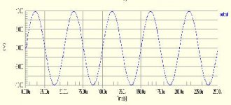
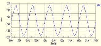
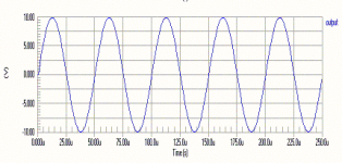
Anyway, I put a 2uf in both circuits, feed with 1vp 20khz sine signals.
THD: 5.50% for BJT, and 0.11% for MOSFET.
gain shoot up 2x higher than normal at 200khz for both amps. The output from the MOSFET remains visually perfect while that of the BJT looks like triangular.
Here is the MOSFET output, taken at the speaker terminal.
Attachments
.
 ...
...
Hi Graham,
You are opening a whole box of cans of worms here.. ;-) Some of your conserns are shared by me, both some other I don't understand. While I would love to discuse all that should be considderd when building a very high quality amplifier I don't think that is practical . I hope you will agree that it'smore pratical for me if I narrow my efforts down to: ‘Evaluate the effects of the IRF540 MOSFET substitutions for the 2N3055 output transistors in a JLH 1969 amplifier' .. This is giving me problems enough
I was hoping you could develop such a protocol. I don't think I understand you well enough to do that.
Indeed I think the THD of the 1969 can be made lower with circuit adjustment and I'would be interested in such a modified circuit. I think Rod Elliots (www.sound.au.com check DOZ) has been that road and succeded in bettering the JLH 1969.
You are right again here, and the tests are of limmited pratical use, but they do provide a methode to evaluate what's happing in the circuit. It help me to find out about the crossconduction. And don't forget, some of us might be using NonOverSample DAC which can produce very sharp transients.
G'night,
Thijs
Just a few thoughts
... Hi Graham,
You are opening a whole box of cans of worms here.. ;-) Some of your conserns are shared by me, both some other I don't understand. While I would love to discuse all that should be considderd when building a very high quality amplifier I don't think that is practical . I hope you will agree that it'smore pratical for me if I narrow my efforts down to: ‘Evaluate the effects of the IRF540 MOSFET substitutions for the 2N3055 output transistors in a JLH 1969 amplifier' .. This is giving me problems enough
Can I suggest that you develop a protocol that includes first cycle distortion testing, as well as conventional measurement, because this will include all circuit weaknesses.
I was hoping you could develop such a protocol. I don't think I understand you well enough to do that.
... the matching of output devices and driver resistors plus a more powerful driver can make the bipolar JLH run with lower distortion, than has so far been reported.
Indeed I think the THD of the 1969 can be made lower with circuit adjustment and I'would be interested in such a modified circuit. I think Rod Elliots (www.sound.au.com check DOZ) has been that road and succeded in bettering the JLH 1969.
With regards to squarewave testing, there is nothing in audio as fast as a computer simulated squarewave. A square wave induces cross conduction and overshoot where real audio cannot
You are right again here, and the tests are of limmited pratical use, but they do provide a methode to evaluate what's happing in the circuit. It help me to find out about the crossconduction. And don't forget, some of us might be using NonOverSample DAC which can produce very sharp transients.
G'night,
Thijs
Hi Millwood,
Indeed the higher peak output current and higher slewrate of the MOSFET version does show them self in your test. This should be considerd an improvement I think over the original 1969 version.
Have you tried a high frequency square wave yet with both circuits and some capacitance to ground? Could be reveiling too.
G'night,
Thijs
tschrama said:Have you tried a high frequency square wave yet with both circuits and some capacitance to ground?
G'night,
Thijs
I haven't been able to find a square voltage source in protel dxp to drive my circuitry, 🙁.
Any tips?
- Home
- Amplifiers
- Solid State
- JLH 10 Watt class A amplifier