Regards to Somerset; born there early 60 yrs ago and was visiting last November.......did you know JLH lived in Taunton for many years?
Yes, evidence points to JLH having lived in Taunton; most of his WW letters are signed off as JLH, Taunton, Somerset.
I'm sure I read somewhere his house was called 'Robins' (Robin Hood, geddit)
There really was no-one quite like him, or will ever be again.

Re high current at turn on. The original article and the subsequent "WW" 15-20 watt Class AB circuit both had largish thermistors in the AC line to the primary. They were CZ numbers I think. That was for relatively small PS caps. More important as of late with much higher values being used. Jung also published a circuit with a timer to limit voltage at turn on. It was "AUDIO" (US) from way back (80's) but there must be other diy "soft start" schematics around.
Hellow Everybody,
My first post after joining DIY forum. Just completed reading all 187 pages (1863 posts) of this thread.
Built a JLLH way back in the 70s, with 1711 & 3055s, Home wound transformer, Home made heat sinks from a design from Mullard, Burrows preamp. Did not touch a soldering iron for 30 years.
Time to start dedusting the old amp and getting a new soldering iron!
--gannaji.
Member
Joined 2009
Paid Member
Welcome Gannaji,
Will look forward to reading your exploits if you decide to construct a JLH.
All people on this thread seem friendly and helpful and have given me lots of advice. Am in the process of building a 20 watt version and if I knew how to post some pictures I would ( help )
Go on Gannaji, get that soldering iron heated up.
Alan
Alan,
You need to click 'Go Advanced' at the bottom of this page and then click 'manage attachments' to open a pop up window where you can add pics. There is a limit on the size of the file.
Gannaji, go on and show us pics!
You need to click 'Go Advanced' at the bottom of this page and then click 'manage attachments' to open a pop up window where you can add pics. There is a limit on the size of the file.
Gannaji, go on and show us pics!
Old JLLH photos
Now that I could successfully upload the first photo, here are three more.
For some boring details:
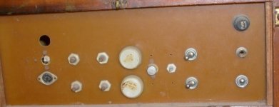
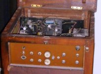
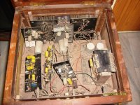
Myself and my friend (Bachelor at that time) did this as a joint venture. He brought all the materials from Delhi. We assembled as follows. Taken paper based phenolic board, (6 nos), stick graph paper to them, drew the circuit diagram, drilled the holes and assembled exactly as per the diagram lay out. Each channel consists of one preamp board (Burrows), one buffer cum low-high pass board and one Power amplifier board. All the six boards were spreadout on his dining table along with four heat sinks, connected to Two loud speakers, known as Mellow Monsters, constructed from an American DIY magazine. The signal source was a Philips record player with ceramic pickup. This was like that for a few years. In 80, my friend emigrated to US and the boards and Loudspeakers were left with me. Then I assembled the whole thing into a wooden Box and used it for around 8 years.
The circuit used was the one given by JLLH in a letter to use 3055 and 1711 as VAS or phase splitter.There used to be a slight switch on thump. There was also slight hum when heard with ears within 12 inches of the loud speakers. Else, the whole system was very enjoyable.
--gannaji
Now that I could successfully upload the first photo, here are three more.
For some boring details:
Myself and my friend (Bachelor at that time) did this as a joint venture. He brought all the materials from Delhi. We assembled as follows. Taken paper based phenolic board, (6 nos), stick graph paper to them, drew the circuit diagram, drilled the holes and assembled exactly as per the diagram lay out. Each channel consists of one preamp board (Burrows), one buffer cum low-high pass board and one Power amplifier board. All the six boards were spreadout on his dining table along with four heat sinks, connected to Two loud speakers, known as Mellow Monsters, constructed from an American DIY magazine. The signal source was a Philips record player with ceramic pickup. This was like that for a few years. In 80, my friend emigrated to US and the boards and Loudspeakers were left with me. Then I assembled the whole thing into a wooden Box and used it for around 8 years.
The circuit used was the one given by JLLH in a letter to use 3055 and 1711 as VAS or phase splitter.There used to be a slight switch on thump. There was also slight hum when heard with ears within 12 inches of the loud speakers. Else, the whole system was very enjoyable.
--gannaji
Attachments

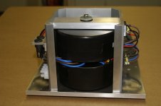
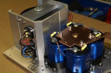
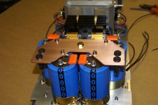
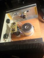
Hi everyone, i have started to construct the power supply ( rightly or wrongly, comments please ) Here is a rundown of progress so far.
2 x 300VA torroids suspended in rubber bushes in an aluminium housing.
2 x 25 Amp bridges for each torroid.
4 x 10,000 uF electrolitics.
4 x 1 OHM 25 watt resistors.
4 x 100,000 uF electrolitics
0.1uf bypass caps.
Fuses on primary of torroids
Fuses before amplifiers
This is all housed in a chassis made of 10mm aluminium plate, 400mm long x 250mm wide x 150mm high. heatsinks will be mounted along both long sides ( heatsinks are 400x 150x40 ).
I will try to post some pics of the work so far, have not posted pics before so appologies if I get it wrong.
Alan
Attachments
-
 PICT0243 email.jpg137.9 KB · Views: 958
 -
 PICT0245 email.jpg263.4 KB · Views: 504
 -
 PICT0248 email.jpg278.2 KB · Views: 488
 -
 PICT0250email.jpg282.1 KB · Views: 452
 -
 PICT0252email.jpg309.4 KB · Views: 481
 -
 PICT0255email.jpg294.3 KB · Views: 462
 -
 PICT0257email.jpg281.1 KB · Views: 484
 -
 PICT0258email.jpg262.2 KB · Views: 506
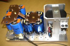
So fine and neat
Wow,
It looks so nice Alan.
Please keep us posted I can not wait to see the final product.
Wow,
It looks so nice Alan.
Please keep us posted I can not wait to see the final product.
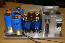
Looks amazing . . . but when it's all connected up to the amp try putting 0.1uF + 47 ohms across each transformer secondary and see if it sounds better.
In my experience it always does and the difference is not small
good luck
mike
In my experience it always does and the difference is not small
good luck
mike
Member
Joined 2009
Paid Member
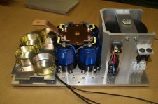
it looks to me that you have a shorted turn on that toroid 😱
Edit: phew - noticed the insulated washers for the bolt.
Looking good !
Edit: phew - noticed the insulated washers for the bolt.
Looking good !
I saw this too, but looks like the top toroid is bolted to top plate, while bottom toroid is bolted to bottom plate. There should not be single bolt going through both toroids...or else you will have shorted turn...
EDIT - or the washers...
EDIT - or the washers...
Last edited:
Hi all, thanks for looking at the pictures. The torroids are suspended by 8mm threaded rod. The rod passes through both and is well insulated top and bottom from the chassis to avoid shorted turn problem. I have mounted the torroids like this to prevent any noise or vibration from them. Seems to work OK as I can put my ear really close when they are on and can't hear a thing.
Will post some more pics as I progress, but it may be a while.
Alan
Will post some more pics as I progress, but it may be a while.
Alan
Hi, I forgot to ask in my last post---MIKELM, 47ohm resistor, what sort of wattage please. Any other advice or help gladly recieved.
Thanks
Alan
Thanks
Alan
HI Ulis
Rectifier diodes require no heatsink?
Hi
Rectifier have been established later
- Home
- Amplifiers
- Solid State
- JLH 10 Watt class A amplifier