I'm not going to use split supplies, so I will have an output condenser.
If in 5, 10 or 15 years you get around to making a more recent, DC linked version of this amp you may be kicking yourself for not having done it originally - the difference in sound quality is not small.
An output "fuse" made of suitable size constantan resistance wire soldered between two PCB posts 0.1 - 0.2 ohms will also protect your speaker and in my opinion does not compromise sound.
Anyway, whatever route you choose I wish you well
mike
One of the better iterations of this amp, IMO is the plain '69 version with a dual supply tacked on.
Wow the thread has burst into life again, keep it going, the more I read the more I learn.
With you on that mikelm.
My project has slowed down due to too many other boring jobs. That's life.
Thanks all.
alan.
With you on that mikelm.
My project has slowed down due to too many other boring jobs. That's life.
Thanks all.
alan.
Member
Joined 2009
Paid Member
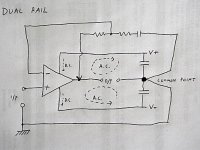
Dual Rail Supply
I still need to understand something here.
I've attached a simple dual rail supply schematic. It's not the conventional way to draw an amplifier with nfb but I want to make some points.
The signal input is a voltage, sharing a common point of reference to the output. The signal input is a single ended signal over an RCA-connected cable and we assume that the shield of the cable is, practically speaking, connected to the chasis of your source and the chasis of your amplifier (potentially via a ground isolating resistor bypassed by a diode to reduce ground loop hum).
The d.c. current from the power supply flows through the amplifier as shown. With no input signal the amplifier output should be at the same potential as the Common Point so that no dc flows through the speaker and the power supply.
The a.c. signal current in the JLH flows through both upper and lower output devices - call it push-pull or not. Since current flows in closed loops there must be two of them, each including the load and one of the output devices. I've shown these a.c. signal loops. We see that a.c. current must flow through both of the power supply rail capacitors. So we see that a dual rail amplifier does not remove large electrolytic caps out of the load current path.
But we don't find this is a problem because distortion introduced by these caps is reduced to negligible levels because the amplifier has plenty of nfb to correct for it. The nfb network samples the voltage signal at the output from the amplifier - shown by the arrow - and feeds a portion back to the inverting input of the amplifier.
OK so far ?
Attachments
Member
Joined 2009
Paid Member
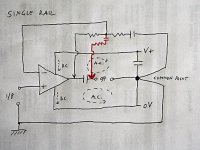
Now I've attached a similar schematic, but this time the original single rail JLH amplifier.
This time we can see that again, the a.c. signal current flows in two closed loops. One of them flows through the output capacitor. The other one flows through both the output capacitor and the power supply rail capacitor. As with the dual rail version, we have two capacitors in the speaker load a.c. current path.
But people say the single version sounds worse. Why ?
I think it may because the distortion in one of these capacitors is no longer adequately corrected for by the nfb. The nfb is sampled at the output of the amplifier as before, shown by an arrow, but this means it doesn't sample the distortion introduced by the output capacitor and therefore can not correct for it.
So I go back to my earlier question - if my understanding of how the amplifier with dual rails and single rail works, the issue is the nfb take off point.
A possible solution is to move the nfb take off point to the load side of the output capacitor, shown by the red arrow. In principle, this should allow the nfb network to correct for the distortion of the output capacitor. There are problems with phase-shifts when capacitors are part of the nfb loop (and potential motor-boating), so a practical design uses a combination of both nfb take off points.
Has anyone tried this - can it make the single rail amplifier sound as good as a dual rail amplifier ????????????
Attachments
Last edited:
I think you have analysed the amp topology quite well but I think that even if you figure out how to have a dual feedback system the resultant o/p will still be the product of the two f/b paths and not purely the f/b from the far side of the o/p cap - so the result will also me a mix and not as pure as a single f/b loop in an amp without an o/p cap.
Also in both of your diagrams there is an electrolytic cap in the feedback path which will introduce it's own limitations to how accurately the feedback loop can function. This is clearly audible when you remove it.
Have you checked out Geoff's site to see the different versions he shows there ? I think there is a link above somewhere a few posts up - well worth a read
cheers
mike
To make a single rail amp as good as a I would take a balanced signal all the way from the DAC or other source.
Have two amps per channel, one for each phase with an earth defined with two equal resistors across the rails and smoothed with an electrolytic.
this means:
speaker is then driven by two amplifier o/p's with no caps
DC feedback with no caps
i/p signal DC linked also with no caps
1/2 - 2/3 rail voltages only needed for same o/p swing.
perhaps also common mode noise will be cancelled
how's that sound to you ?
Hi Bigun
ONe reason that the SE version might sound worse is due to poor LF response. It is not clear to me when people say that capacitor coupled designs are worse what the problems are - whether they are HF or LF part of the audio spectrum.
Modern low-ESR, ESL capacitors should be far better than the older types. I've even had some old types which sing along with the music -that has to be introducing distortion.
Even with good caps the size is too small. With the usual 2.2 mF (or 2200 mfd as it used to be known) leading edge bass transients are hopelessly attenuated. YOu need larger ones, as was point out to me some time ago. 22 mF starts to get close.
THe second point about the original JLH is that the output transistors need to be faster than 2N3055 was back then. A modern epi 2n3055 should be better, but the bootstrap can only work as fast as the output - so if the output is slow, so is the amp. WIth the second version of JLH with a current source the output can be pulled faster.
John
John
Member
Joined 2009
Paid Member
I don't fancy going the whole hog with a balanced signal - I don't really have a suitable source or cables and it would be incompatible with the rest of my gear. Perhaps viable in the long term but not for my first JLH.
If we agree that the single rail can't completely replicate the dual rail set up in terms of nfb correction then it comes down to a choice between a) virtual earth supply - since my trafo has no centre tap, b) better quality output capacitor.
The original JLH uses relatively small value output caps compared to those used for rail decoupling so this is already an issue - D Self has shown that distortion from the capacitor remains low until the a.c. voltage across the cap starts to increase (i.e. the l.f.. roll off). Very large value caps would therefore diminish the distortion problem - Nelson Pass recommends such an approach for his Zen amplifiers.
Ever considered good quality double bi-polar ? - if not, read these:
http://www.diycore.com/patrick/files/electronics/capacitor/capsound5.pdf
http://www.diycore.com/patrick/files/electronics/capacitor/capsound6.pdf
Who has tried really good output caps and still found dual rail better ?
Edit: just saw John's post. Looks like we're both thinking the same about the need for Big capacitors. John - I'm not considering the 1996 design with current sources at this point, just the original '69 although I will entertain dual rails. I guess there are many changes and improvements possible so I have to draw a line somewhere and using a CCS is a casualty of this choice. I have some objections to the CCS too - it places another active device into contact with the signal (if you think carefully) and increases OLG which I don't wish.
Last edited:
Who has tried really good output caps and still found dual rail better ?
I haven't done such a study, but I'd feel fine about using a single supply version as a tweeter amp in an active setup. I.e: the mandatory output capacitor could be the crossover component...a nice poly cap... and an input capacitor would be optional but useful.
To clarify, I am using one of the active supply variants. The output capacitor at the output of the capacitance multipliers on that page are obviously partially swamped by the regs.
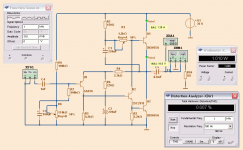
In the JLH Class A original I have tried THD distortion.
When I replaced 2N1711 with 2SC2911 at 1 Watt level
the THD changed from 0.103% to 0.007%.
Conclusion is that to avoid 2N1711 and go for
a transistor like 2SC2911 in that place.
2SC2911 is even considerably better than BD139 in this circuit.
See diagram for the updated JLH Class A.
When I replaced 2N1711 with 2SC2911 at 1 Watt level
the THD changed from 0.103% to 0.007%.
Conclusion is that to avoid 2N1711 and go for
a transistor like 2SC2911 in that place.
2SC2911 is even considerably better than BD139 in this circuit.
See diagram for the updated JLH Class A.
Attachments
I haven't done such a study, but I'd feel fine about using a single supply version as a tweeter amp in an active setup. I.e: the mandatory output capacitor could be the crossover component...a nice poly cap... and an input capacitor would be optional but useful.
I agree with this idea - I have found that caps seem more "invisible" in low impedance high current environments i.e. X-overs but after trying some reasonably expensive "audiophile" caps as input caps my conclusion is that it is more "useful" in sound quality / clarity terms to avoid them altogether if at all possible.
I have to say that I did not try teflon types yet so can't comment on them.
but I am aware that different people have different tastes in the sounds of their audios so it may be your conclusions would be different
Member
Joined 2009
Paid Member
In the JLH Class A original I have tried THD distortion.
When I replaced 2N1711 with 2SC2911 at 1 Watt level
the THD changed from 0.103% to 0.007%.
Conclusion is that to avoid 2N1711 and go for
a transistor like 2SC2911 in that place.
2SC2911 is even considerably better than BD139 in this circuit.
See diagram for the updated JLH Class A.
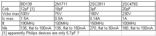
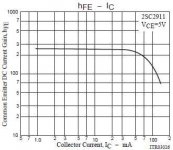
I checked out the data sheet to make some comparisons (attached) - the main concern I have is the 2N1711 has limited current capability and you see this in beta droop above 50mA. The BD139 looks more robust from this perspective.
Attachments
Member
Joined 2009
Paid Member
BD139 SPICE better then 2N1711, too.
But 2SC2911 is yet another level better.
with
1N1711 - 0.203% THD
BD139 - 0.050% THD
2SC2911 - 0.007%
This shows at least, that transistor in this place of the amp
is of great importance for good performance.
Bigun.
That beta curve of 2SC2911 looks nice, to me.
If curve is flat to 50mA, I think it is enough. Depends on the gain of output devices.
We see that the capacitance is where 2SC2911 wins.
Maybe this is importance.
Last edited:
Member
Joined 2009
Paid Member
Well it looks like my usual supplier (digikey) does not carry these little three legged wonders (2SC2911)
But on the positive side of life, I have decided after all the good advice received, to implement the '69 with dual rails. I'll build a Virtual Earth circuit like the one attached (from Nico Ras on the AKSA headamp thread)
But on the positive side of life, I have decided after all the good advice received, to implement the '69 with dual rails. I'll build a Virtual Earth circuit like the one attached (from Nico Ras on the AKSA headamp thread)
Attachments
I'm pretty sure that you can't drive an 8ohm speaker to your lightish weight virtual earth. My guess is that you will at least need darlingtons to sink enough current without compromising the integrity of the earth - but please would others please comment also because I'm not experienced in this area.
Member
Joined 2009
Paid Member
I figure that the VE only experiences the dc current - and hopefully there ain't much of that flowing through the load. The VE is decoupled by large caps, these handle the large a.c. currents flowing through the load.
well, I'm still 99% certain that this earth will not be strong enough - perhaps you should check with aksa, it's his design, but the clue is I think that this was designed for a headphone amp - for a power amp I would suggest at least Darlingtons & at least 10,000uF Caps
Member
Joined 2009
Paid Member
I think you are right, if there's a dc offset we can quickly see some current flowing. What I will do is beef up the transistors to a pair of BD139/BD140 because this is what's in my junk box. That will allow quite a bit of current flow if dc offset is out of adjustment. I will beef up the capacitors, but put them near the outputs, a pair of caps on each channel.
Another question - the idle current through the input device (JLH lables it TR4) seems low to me if the collector load is as high as 8k2. He had a good reason to do this, but generally I aim for 1mA or more. Any ideas ?
Another question - the idle current through the input device (JLH lables it TR4) seems low to me if the collector load is as high as 8k2. He had a good reason to do this, but generally I aim for 1mA or more. Any ideas ?
- Home
- Amplifiers
- Solid State
- JLH 10 Watt class A amplifier