To get cleaner, more relaxed, 'more and finer coloured' sound;-)But to what purpose?
We could work on transistors even much further, because they are designed without current- and resonance-regarding.
Ahh... I get it. So I just need a hacksaw then I can drain off the Bovis. Hmm.. perhaps I could even make soup with it! Yummy!
I can't see how slitting the copper heatsink tab can bring about any change in the transistor's performance though - it's also the collector terminal and couples any heat to a heatsink, so you may as well make loops in the power supply wires while you're slotting all the power transistor tabs. I guess that's one kind of fun
I can't see how slitting the copper heatsink tab can bring about any change in the transistor's performance though - it's also the collector terminal and couples any heat to a heatsink, so you may as well make loops in the power supply wires while you're slotting all the power transistor tabs. I guess that's one kind of fun
Last edited:
I have a pair of Frugal Horns the Mk3 variety with the original 4 Ohm MA CHP-70's
12v 1.2 Amps and I have to be very careful with the 22k volume pot, not to turn it up much more than about 10 degrees.
https://jlh1969classa.blogspot.com/p/my-build.html
The heat sinks are barely warm.
Cheers - J
12v 1.2 Amps and I have to be very careful with the 22k volume pot, not to turn it up much more than about 10 degrees.
https://jlh1969classa.blogspot.com/p/my-build.html
The heat sinks are barely warm.
Cheers - J
You need that too, and a pure paste of galium arsenium concentrate between the transistor and the heatsink to be on top.Ahh... I get it. So I just need a hacksaw then I can drain off the Bovis. Hmm.. perhaps I could even make soup with it! Yummy!
I can't see how slitting the copper heatsink tab can bring about any change in the transistor's performance though - it's also the collector terminal and couples any heat to a heatsink, so you may as well make loops in the power supply wires while you're slotting all the power transistor tabs. I guess that's one kind of fun

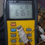
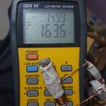
Idea of iron core inductor bad for CLC power supply? Is it better than no L ? And i found a bolt what about winding on it ? Is it a bad idea ? It is about 25grammes of copper 1mm diameter.348uH @100Hz but I can wind more of it and maybe it may be useful for CLC
Attachments


Last edited:
The 12V supply is much too low for 10W output so you're hearing only a few watts and dissipating much less heat than with the recommended 27V supply anyway. You could expect it to run very cool.The heat sinks are barely warm.
Cheers - J
According to the article linked below, you could need something like a 250-500mH choke for either an LC or CLC (pi) filter. That's quite a lot more than 348 uH so are you sure you're reading up sufficiently on this project? Read here why CLC may not be the best type of filter to use either: https://www.jacmusic.com/techcorner/ARTICLES/English/Power-Supply-Design/Index-Note-01.html 00cl
I thought about 1-2 mH may be enough because of Aleph amplifiers use it. 500mH may be too big for air core. And yes English is not my native language and it is very hard for me to read more than 400 pages sorry. Thank you
I have a similar UPS Transformer.It is 2x8v ac transformer.Not single 8v. It makes about 19vdc loaded at 8A.It is minimum 200VA transformer.
Alixpress isn't a reliable source for semiconductors but good for other thing. But yes their price is very attractive.
I thought you're going to use each winding separately. 200VA sounds good.
I’ve successfully used it to power my prototype JLH 69 with a single 18 volt rail and another 69 with dual rail 9-0-9.
With these low voltages I know not going to achieve the 10 Watts that the designer intended but it’s all that I have available to experiment with until I get home where I can source a 500 VA toroidal to build my first JLH & listen to it to along with my first mosfet amplifier that I built in the 80’s which I have managed to keep for nearly 40 years.
William
The article referred to (Power Supply Considerations) is only a few pages of plain text. The rest is diagrams, graphs and a couple of summaries. There is no need to look at the tube power supply comments which refer to high voltages either. So take another look since there is no point in building, making chokes etc. for a project that is doomed to failure before you begin - only because you haven't learnt how it should work yet.I thought about 1-2 mH may be enough because of Aleph amplifiers use it. 500mH may be too big for air core. And yes English is not my native language and it is very hard for me to read more than 400 pages sorry. Thank you
Last edited:
I know that the experience horizon of the vast majority of "High-End"-ambitioned is not very large. But I advise them to check and test all conceivable strange hints - because the most have completed a small common study of electrophysics only, for example. First the practical experience, then the theory.
Advantage: is then also not a thesis only;-)
Advantage: is then also not a thesis only;-)
Hello Ian,The 12V supply is much too low for 10W output so you're hearing only a few watts and dissipating much less heat than with the recommended 27V supply anyway. You could expect it to run very cool. etc
Just popped out to my little listening room, listening to some nice Tango's from the 1920's and checked the voltage going into both amps at 14.5. Or about 5 or six watts.
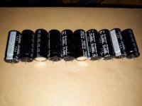
The caps, 40,000 uF's worth, after receiving some advice on this thread stopped the hum.
My db meter indicated 65.2 db average and 71.4 db max while listening to something very loud. My speakers are rated at 85db and working through the 1/2ing of the power comes to 0.01562 and 0.03125 Watts respectively, an 18db transient would need 1 Watt.
It's quite simply the best amp I've ever made and the only one where I listen to the music and not the amp.
Cheers - J
If you lived in the UK I would be delighted if you came and had a listen 🙂

I'd wonder about regulating the supply rather than more and more caps. Suppose it depends on how many transformer volts sone can afford to loose. There are calculators around which predict ripple against capacitors and loads. Class A is a pretty easy job for a regulator as the current is constant.The caps, 40,000 uF's worth, after receiving some advice on this thread stopped the hum.
As it's a more or less a rail to rail drive amp Hood's set up figures for each loudspeaker impedance can simply be scaled based on supply voltage. eg if that is 1/2'd so should the current and power be, Me and a group of people at work knocked one up yonks ago - it seems to be a pretty tolerant circuit.
Thanks for the invite. I'd be delighted 🙂......but don't wait up or be too concerned about my comments on supply voltage. I have built around 15 variations of the '69 JLH myself and helped out and tested another 20 or so - as built by school aged kids and friends over the last 25 years. I built my first JLH long ago - a month or so after the original article in WW magazine finally reached Oz, actually. I used just a 12V power supply to begin with - only because I didn't have the cash to buy a more suitable transformer and caps for the power supply.Hello Ian.....if you lived in the UK I would be delighted if you came and had a listen 🙂
Some of the builds I refer to were quite tiny because the very minimal circuit allows it. They were usually constructed on scraps of "perfboard", matrix board or drilled laminex sheet, with component leads and connecting wires simply soldered together beneath, along with interconnecting leads to signal in/output devices and the power source. Many were powered with only 12V, simply because that was safe and any commonly available automotive battery made a very clean DC power source that was rechargeable, at a time when there were few options such as LiPo or even suitable NiCd batteries available.
It may be surprising to some, but those amplifiers worked and generally sounded just as good with the old silicon transistor types and crude matrix board construction as those high quality epoxy PCBs, higher voltages and split supplies that we now insist on. Yes, agreed - with sensitive 3-4R speakers, you can get quite a lot of volume at 12V and a couple more volts won't make all that much difference. 85db is at the low end of speaker sensitivity though - perhaps you'd like to look at some ideas from Klipsch whose high sensitivity models could add 8-10db to that figure and aren't horrendously expensive. There are other popular brands like Fostex and Mark Audio that supply just the drivers, if you prefer to build your own.
Last edited:
Which option is better in your opinion? I have 40pcs of Rubycon 6800uF 25v 105c capacitors .They measure about 6200uF each. I can make power supply with them.I will not build dual rail.Ac voltage is 16v.It makes 19vdc after rectified and loaded.Nelson suggest CRC but i did not see CRC here but maybe someone can advise if any.
Or i can loose some voltage and make regulator for JLH and think it will drop to 15-16v. I will build this amp for my friend which has limited budget. (i will use UPS power supply and do not buy another transformer)
My friends speakers are 8ohms.Focal 714.
Or i can loose some voltage and make regulator for JLH and think it will drop to 15-16v. I will build this amp for my friend which has limited budget. (i will use UPS power supply and do not buy another transformer)
My friends speakers are 8ohms.Focal 714.
Attachments
Much better than C-Resistor-C sounds a C-Choke-C. Try to use any transformator, e.g. 100 VA, 2 x 12 V. Use the secondary windings. The primary winding you could use to break down the inductivity to hear the effect - per shorting. Then you get CRC only;-)
I would try 4 Caps - Choke - 4 Caps. Should sound very well.
No further little foil caps or so on!
I would try 4 Caps - Choke - 4 Caps. Should sound very well.
No further little foil caps or so on!
It will work fine, just like the original published design without optional smoothing or regulation of the power supply. Build it with the simple power supply shown at Fig.1 of the postscript article (linked below) first, mount it properly in its metal chassis/case and then listen before deciding what is strictly necessary for your friend. http://www.sound-au.com/tcaas/jlh1970.pdf
Use the 2 x 8 V = 16 V winding-s;-)Sorry i can only use my transformer for my friend. It is 2x8vac or 16v ac.
- Home
- Amplifiers
- Solid State
- JLH 10 Watt class A amplifier