
Which option is better in your opinion? I have 40pcs of Rubycon 6800uF 25v 105c capacitors .They measure about 6200uF each. I can make power supply with them.I will not build dual rail.Ac voltage is 16v.It makes 19vdc after rectified and loaded.Nelson suggest CRC but i did not see CRC here but maybe someone can advise if any.
Or i can loose some voltage and make regulator for JLH and think it will drop to 15-16v. I will build this amp for my friend which has limited budget. (i will use UPS power supply and do not buy another transformer)
It will work fine, just like the original published design without optional smoothing or regulation of the power supply. Build it with the simple power supply shown at Fig.1 of the postscript article (linked below) first, mount it properly in its metal chassis/case and then listen before deciding what is strictly necessary for your friend. http://www.sound-au.com/tcaas/jlh1970.pdf
I agree with Ian as the original 1969 & PSU is your best option considering the circumstances of the build Veysel.
My recommendation is :
1. Use the Up Cycled Low Voltage transformer out of a UPS, connect it to a bridge rectifier & use as many of the Capacitors as you can accommodate in the intended enclosure.
2. Choose the 1969 circuit as previously detailed in ( Fig 1 of the postscript article by JLH initially published in December 1970)
Take care with you wiring & use common sense in its placement within the enclosure.
3 Finally Listen to your creation & test & adjust as necessary. You will probably go around in ever decreasing circles & have to make compromises to cross the finishing line.
What’s the most important thing here is to actually build the amplifier, listen to it & get pleasure from something you have built out of available parts not to pontificate over Types of PSU’s , VA ratings of transformers, choice of rectifiers , smoothing Capacitors, or even the difficult decision of which semiconductors to use in a Amplifier of Design that’s had its Golden Anniversary !
I’ve been following this 20 year old thread now for over a year & it’s so easy just to keep reading, researching, then RE circling the same initial design before actually ‘firing up’ the soldering iron to evolve the 1969 off the bread board onto perforated board before deciding on a PCB to create the finished amplifier.
William
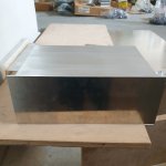
What about transformer position and location? I read vertical positioning the transformer reduces emi radiation by 4dB. Maybe isolating with thin aluminium sheet and make a room for transformer be better for shielding because it radiates more emi than toroidal transformer.Does touching top plate make magnetic loop? Maybe do not do because it is not stell.
Attachments
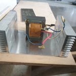
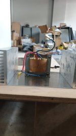
Transformer position first: Listeners and neighbors should get minimal EMF - electromagnetic field:
Toroidaltrafos - look through the hole.
Others, like seen above: bottom and top to listeners and neighbors.
Am I right?
EMF are very harmful to health! And: reduce all your hf-EMF: mobile radiation, WLAN, bluetooth and so on!
Aside: mobile radiation is THE key technology of the new/one world order! REMAINs mobile radiation, COMES the NWO!
What about transformer position and location? I read vertical positioning the transformer reduces emi radiation by 4dB. Maybe isolating with thin aluminium sheet and make a room for transformer be better for shielding because it radiates more emi than toroidal transformer.Does touching top plate make magnetic loop? Maybe do not do because it is not stell.
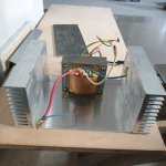
Always think a picture worth many words , since you using aluminium as an enclosure, you may have a problem with Eddie Currents, personally I would insulate all panels & heatsinks & link them all together with a star earth connected to transformer then to your utility earth input to the enclosure.
William
Hello Ian,Thanks for the invite. I'd be delighted 🙂......but don't wait up or be too concerned about my comments on supply voltage. I have built around 15 variations of the '69 JLH myself and helped out and tested another 20 or so - as built by school aged kids and friends over the last 25 years. I built my first JLH long ago - a month or so after the original article in WW magazine finally reached Oz, actually.
Thanks for the message and the story very interesting indeed, I do hope lots of other on this thread read it. It does confirm what I've thought for a long time.
When the Frugal Horn Mk3 drawing was first released, I popped down to the local B&Q shed and got some 18mm MDF 8ft x 4ft they cut it for me free. I bought a pair of Mark Audio CHP-70's from Spectrum Audio in Germany the only place in Europe selling them at the time. Altogether cost about £75.
I was astonished at the performance of the design and have been listening to them for about 12 years and see no reason to change.
Cheers - J
Sorry i do not understand about half of your sentences 🙂Transformer position first: Listeners and neighbors should get minimal EMF - electromagnetic field:
Toroidaltrafos - look through the hole.
Others, like seen above: bottom and top to listeners and neighbors.
Am I right?
EMF are very harmful to health! And: reduce all your hf-EMF: mobile radiation, WLAN, bluetooth and so on!
Aside: mobile radiation is THE key technology of the new/one world order! REMAINs mobile radiation, COMES the NWO!


It's normal, it means you're fine, only Cumbb understands cumbb.Sorry i do not understand about half of your sentences 🙂
I really like the design that this guy chose, it changes from the classics.
I've been thinking for a long time that I'm going to do something like that, a piece of art.
https://ldsound.info/jlh-open-mount-amplifier/
I've been thinking for a long time that I'm going to do something like that, a piece of art.
https://ldsound.info/jlh-open-mount-amplifier/
Design is nice. Can i make amp with constant current led power supply? It is Ldx75-1400. I have 10 of them but could not use them yet. Maybe i can build amp for myself too.
I only matched Idss of Irfp240 with CCS. Have not built an amp yet. What will be the voltage,i am not sure.
I tried, I have several SMPS TDK LAMBDA, some prefer, I did not like and stayed in the classic CRC.Design is nice. Can i make amp with constant current led power supply? It is Ldx75-1400. I have 10 of them but could not use them yet. Maybe i can build amp for myself too.
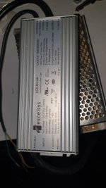
Your PSU would need to have only a fixed voltage output to make it a regulated power supply for an amplifier. You already know that the amplifier needs to draw a variable current, according to the fixed DC bias current+the AC instantaneous audio output current. Otherwise, if you have a continuous fixed DC current, you won't hear much audio. The specified transformer rating could be used to determine how big the PSU needs to be for whatever output voltage you require.
I think we can assume that for LED power, the 1.4A PSU limit is actually the maximum continuous output current rating of the power supply. If you use most of that current just to bias the amplifier, there would be little audio output, since that requires additional, modulated current capacity to drive the speaker with the full AC signal voltage also required.
I think we can assume that for LED power, the 1.4A PSU limit is actually the maximum continuous output current rating of the power supply. If you use most of that current just to bias the amplifier, there would be little audio output, since that requires additional, modulated current capacity to drive the speaker with the full AC signal voltage also required.
Last edited:
- Home
- Amplifiers
- Solid State
- JLH 10 Watt class A amplifier