That circuit shows it is really quite simple to measure the gain of a transistor.
For a power transistor you might want the ammeter to read up to 10A.
You can build a simple gain tester with a multi-way switch to change the resistors in the base.
I usually do not use a resistor in the collector so that the collector voltage is fixed. (but there is a sense resistor in the emitter for the set-up below)
I use an ex-computer PSU with 5V/20A to provide the power.
It is essential to bolt any power transistor to a large heatsink (5V4A=20W) and make the test as quickly as possible. Gain changes with temperature, as does Vbe but at 5V supply it's manageable.
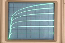
One of the projects still on my "to do" list is a pulse tester which would need low value resistors to measure the high current on an oscilloscope. I already use a similar configuration to turn a scope into a curve tracer.
This image looks like a curve tracer but is in fact a multiple exposure with each curve a different base current. (Yes, I know, it's a slow-mo curve tracer! But those old Teks are hard to find).
For a power transistor you might want the ammeter to read up to 10A.
You can build a simple gain tester with a multi-way switch to change the resistors in the base.
I usually do not use a resistor in the collector so that the collector voltage is fixed. (but there is a sense resistor in the emitter for the set-up below)
I use an ex-computer PSU with 5V/20A to provide the power.
It is essential to bolt any power transistor to a large heatsink (5V4A=20W) and make the test as quickly as possible. Gain changes with temperature, as does Vbe but at 5V supply it's manageable.
One of the projects still on my "to do" list is a pulse tester which would need low value resistors to measure the high current on an oscilloscope. I already use a similar configuration to turn a scope into a curve tracer.
This image looks like a curve tracer but is in fact a multiple exposure with each curve a different base current. (Yes, I know, it's a slow-mo curve tracer! But those old Teks are hard to find).
Attachments
Hi Polsol
A very neat construction. 🙂
I hope you are pleased with the sound.
Kind regards
Mike
Thanks Mike,
As mentioned elsewhere I have changed it somewhat using Bonsai's Ripple Eater and further simplification.
The one shown had significant 50Hz hum - why I changed the PSU(s).
I'll take a new photo when I open the box again and update.
Otherwise, love the high frequencies, very smooth but the bass is a little lacking. It might be that the shared RE only has 10,000 uF per channel (which I intend to increase at some time). The transformer is also only 160 VA which might be a little small.
Cheers,
Tony
Attached is a picture of the JLH amp I built some time back. It has since been modified - I removed the soft start board (left rear), "Ground Lift" (Right Rear) and the twin PSU's (Centre front). The twin PSU has been replaced by one of Bonsai's Ripple Eaters which feeds both amps.
The output trannies are mounted on Aluminium 'L' brackets on both sides. The 'L' bracket is positioned roughly 1/3 from the bottom of the heatsinks.
The two output transistors are equally spaced on each bracket.
The case is a Modushop 2U. With ± 15V DC supply and 1.5 Amp bias, the heatsinks run at around 30°C above ambient.
Hope this helps.
Another beautiful build Tony! Very nice looking amp!
Another beautiful build Tony! Very nice looking amp!
Thanks Bonsai,
Your Ripple Eater really slugs the hum over the original dual PSU (2 by 10,000uF per rail) but with a single RE and only 10,000uF 'shared' between both channels I think the bass suffers (and the 160VA ±15V transformer is probably not helping). What do you think? (Reminder I used 10,000uF 'cans' because I couldn't get anything higher at 50V with the max diameter allowed on the PCB when used for your xK Amp in AAB mode running at ± 35V). Now I have a lower rail voltage of just ± 15V I can look for a lower voltage electrolytic with higher uF 🙂
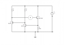
manel - here is the test circuit with the ammeter added. The current should be set to 100mA if you don't have an autoranging meter.
This determines the base current needed for the transistor to pass 3A (this current can be checked by measuring the voltage across the emitter resistor).
The base current is therefore needed in the circuit to drive the upper output transistor at full current. That is set by R1 and R2 (plus any other series resistor like R12 in Prasi's diagram).
You need to add a small margin so that the driver transistor does not cut off completely.
That would be something like 10-15% extra, but any increase has a direct impact in output dissipation, and standing current, of course.
In Prasi's circuit if the base current of the MJL21194 is 50mA, say, then adding 10% means 55mA in the resistors. The supply voltage is 24V so the voltage across the resistors is half this, less a Vbe of the upper output transistor, or about 11.4V.
That makes the resistances needed total 11.4/55mA=207 ohms. These can be split 50:50 but reducing R1 generally helps. In Prasi's circuit R1 is 47 ohms, and R2+R12 is the remainer at 160 ohms, though probably the 10 ohm is not really necessary - but the output stage current will increase a little if omitted.
Thanks John, I appreciate your inputs. As you can see I'm still struggling with the same topic since I asked you long time ago. I'm attaching the circuit you showed me. It didn't work for me, but that was long ago and I don't recall why. I'll try again.
I have been listening music and radio on my JLH amps since then, but I guess there's room for improving and fine tuning. I have to say that I'm really please with this amp.
Thanks again.
Manel
Attachments
@ Manel.
if you set foot in the search for the best transistors and the best balance for your JLH, you will enter a world of madness.
I rode my first JLH (which I use almost every day since) it is a little over ten years old, and now I no longer count my transistors in number, but in weight 🙂.
this amp is certainly not the best and does not do everything perfectly well, but it is so pleasant to listen to and never tiring that for nothing in the world I would not part with it.
recently I got my hands on a lot of completely forgotten transistors (180T2s) and it rekindled the flame for a new build.
Hy!
Interesting, question ...
I see on the net KRELL, NOBSOUND JLH in pnp design.
Based on the images, a 1969 JLH was built with a stabilized (adjustable?) Pass stabilizer and pnp (MJ2955) terminating transistors. I think they turned over the other transistors too, or I don't know how and why it was made with pnp ends. That another business trick is evident.
Does anyone know more about this solution? I'm only interested in quantum, the traditional design is good for me ...
2020 Breeze Audio Voice King Hood 1969 Golden Sealed Real Class A Home Audio Power Amplifier 15W+15W Warm Sound AC110V Optional|hood 1969|breeze audio1969 class a - AliExpress
@ Manel.
if you set foot in the search for the best transistors and the best balance for your JLH, you will enter a world of madness.
I rode my first JLH (which I use almost every day since) it is a little over ten years old, and now I no longer count my transistors in number, but in weight 🙂.
this amp is certainly not the best and does not do everything perfectly well, but it is so pleasant to listen to and never tiring that for nothing in the world I would not part with it.
recently I got my hands on a lot of completely forgotten transistors (180T2s) and it rekindled the flame for a new build.
I know what you mean. I think soldering must be addictive. It might be better to move on to another project and leave it as it is. Thanks for the advice
I think it's because of the higher gain of the pnp transistorsHy!
Interesting, question ...
I see on the net KRELL, NOBSOUND JLH in pnp design.
Based on the images, a 1969 JLH was built with a stabilized (adjustable?) Pass stabilizer and pnp (MJ2955) terminating transistors. I think they turned over the other transistors too, or I don't know how and why it was made with pnp ends. That another business trick is evident.
Does anyone know more about this solution? I'm only interested in quantum, the traditional design is good for me ...
2020 Breeze Audio Voice King Hood 1969 Golden Sealed Real Class A Home Audio Power Amplifier 15W+15W Warm Sound AC110V Optional|hood 1969|breeze audio1969 class a - AliExpress
there is a mosfet version. I bought a kit a long time ago but never assembled it, I devoted myself to the assembly of the first ACA
This is an option with a capacitance multiplier and an inverted supply polarity. Collected from the parts that were in the warehouse 🙂
Yes, there could be a truckload of MJ2955 left after selling so many 2N3055 😉
I have that gold coloured "KRELL" branded clone. It was cheaper than buying a case, parts and building it myself. A friend later bought the 2N2955 (negative polarity) version and we tried to compare them, side by side, using the same source and speakers, with each test being controlled and concealed by the other listener, located in the next room.
It was a quick and dirty way of checking for expectation bias (probably the largest problem when evaluating audio products). The result was that he preferred my amp but I liked his better - an unexpected result but we discussed this many times and still don't know why we decided against our own notions of what makes good audio sound quality. We did the test again and again with weeks and months between but no conclusive results because we made different choices, sometimes the same, sometimes different.
Conclusion:- any difference in the behaviour of the inverted polarity semis with power supply filtering is too small to be important for this design in normal use. I haven't properly checked this any further but similar sized/type amplifiers in class AB, could give very different results due to the crossover artefacts.
Last edited:
so i have seen a lot of these builds over the years, and built my own using the modded china boards, has any built one to the original schematic and using the mj480 transistors. i have a few of the mj480s and thinking of building one.
Look after those MJ480's!
They seem to be quite fragile. Had a few 481/491's for Bailey's amp once, and despite SC protection still managed to blow them up. Don't think I have any survivors in my old TO-3 store.
They may be better off in a Class A amp with limited base drive. But it was a concern of mine in the JLH'69 that there seems to be a distinct possibility of reverse biasing the upper output device base junction.
Despite the few I've built, I have never really settled on it as a main hifi amp. Not sure why, but the sound never seemed quite "good enough" when it came to complex orchestral sounds. But very good for single instruments, voices, so I guess it depends on people's listening choices to some extent.
totally agree about orchestras and complex and / or fast music, it is not made for that, well I think, but on the other hand on vocals and instruments alone, it's a real pleasure
i found these boards on ebay and the curcuit looks like the original schematic, i have ordered some to see what there like. would save a lot of time making them.
10W x2 One pair JLH HOOD1969 Stereo Class A Audio Power Amplifier 2.0 Mirror PCB | eBay
10W x2 One pair JLH HOOD1969 Stereo Class A Audio Power Amplifier 2.0 Mirror PCB | eBay
i have a lot of pcb in different version but i would like so much to have the time to assemble one in p2p.
tell me when you have received if the quality and schématic is ok
tell me when you have received if the quality and schématic is ok
Hi guys, I built my JLH 1969 (10W) monoblock amplifier.
I set up 2 amplifiers to make stereo.
Power supply:
Transformer: 110V / 220V (60Hz) / 0+18V AC 6A
Rectifier bridge: 8A
Capacitor: 22,000uF (63V)
Power on amplifier board: 18V DC
Bias (I.Q.) = 2A
Distortion-free maximum power (1kHz) = 7W rms (per channel)
Distortion-free maximum signal input (1kHz) = 524mV (-3.5dB)
Maximum undistorted signal output (1kHz) = 6.45V
Speakers = 6 ohms
Temperature in components:
Amplifier on for 2 hours.
Ambient temperature = 25°C
Transistor 2SC5200 = 55ºC
2SC5200 heat sink = 40°C
Rectifier bridge = 51°C
Rectifier bridge heat sink = 39°C
Transformer temperature = 40°C
Videos showing the amplifier and tests:
TESTE #8 - Amplificador "CLASSE A" PURO ? JLH 1969 (10W) ? 18V DC e BIAS de 2A - MONOBLOCO - YouTube
TESTE #6 - Amplificador CLASSE A - JLH 1969 (10W) 18V DC e 1,8A - MONOBLOCO (2x) STEREO - YouTube
Circuit diagram PDF:
Update your browser to use Google Drive, Docs, Sheets, Sites, Slides, and Forms - Google Drive Help
...Despite the few I've built, I have never really settled on it as a main hifi amp. Not sure why, but the sound never seemed quite "good enough" when it came to complex orchestral sounds. But very good for single instruments, voices, so I guess it depends on people's listening choices to some extent.
I'm curios about them. Did you build or buy them?
Thanks
Manel
- Home
- Amplifiers
- Solid State
- JLH 10 Watt class A amplifier