Advice how to mount TO-3 powertran to heatsink
Hello!
I have built a JLH class A amplifier (updated vers 2003). Now it is time to put the amp in chassi, Dissipante 4U 300mm from Modushop.biz (modushop.biz/site/index.php?route=product/product&path=207_277_279&product_id=220)
There will be one chassi per channel, ie in total two chassis (Left & Right).
Heatsinks are included in this chassi.
The power transistors MJ15003 is TO-3, in total 2 per channel.
Q: How can I best mount the TO-3 to the heatsinks?
Thanx in advance!
/Fartblind

Some people used an additional aluminum corner with a thickness of 5mm or more.
Don't forget thermal pads and thermal grease.
Last edited:
Hello!
There will be one chassi per channel, ie in total two chassis (Left & Right).
Heatsinks are included in this chassi.
The power transistors MJ15003 is TO-3, in total 2 per channel.
Q: How can I best mount the TO-3 to the heatsinks?
Thanx in advance!
/Fartblind
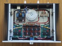
Attached is a picture of the JLH amp I built some time back. It has since been modified - I removed the soft start board (left rear), "Ground Lift" (Right Rear) and the twin PSU's (Centre front). The twin PSU has been replaced by one of Bonsai's Ripple Eaters which feeds both amps.
The output trannies are mounted on Aluminium 'L' brackets on both sides. The 'L' bracket is positioned roughly 1/3 from the bottom of the heatsinks.
The two output transistors are equally spaced on each bracket.
The case is a Modushop 2U. With ± 15V DC supply and 1.5 Amp bias, the heatsinks run at around 30°C above ambient.
Hope this helps.
Attachments

Thank you both!
L-bracket/corner - it will be used.
Polsol: Really neatly done. Inspirational!
1) Did you have to drill new holes in the heat sinks or were there some pre-made holes you could use? 3) What type of screws did you use? 2) Is the heat sink length 300mm ie a the chassi a Dissepante 2U 300?
L-bracket/corner - it will be used.
Polsol: Really neatly done. Inspirational!
1) Did you have to drill new holes in the heat sinks or were there some pre-made holes you could use? 3) What type of screws did you use? 2) Is the heat sink length 300mm ie a the chassi a Dissepante 2U 300?
Thank you both!
L-bracket/corner - it will be used.
Polsol: Really neatly done. Inspirational!
1) Did you have to drill new holes in the heat sinks or were there some pre-made holes you could use? 3) What type of screws did you use? 2) Is the heat sink length 300mm ie a the chassi a Dissepante 2U 300?
I purchased an off-cut of 'L' shaped aluminium extrusion from a local supplier and drilled the TO-3 holes myself using a TO-3 insulator as a template. As OldDIY has mentioned, the thicker the extrusion the better.
The chassis is the 300 mm deep Modushop one and I ran the 'brackets' to hold the output transistors (almost, but allowed for 'space' at either end for wiring/sockets etc on the rear panel) along the length of the heatsinks and secured at multiple points to ensure a 'tight fit'.
Thermal compound was used between the bracket and heatsink to ensure good thermal contact between the aluminium brackets and heatsink. The bolts used to attach the bracket/extrusion to the heatsink, from memory, were probably M4. The holes in the extrusion would have been 4.5mm and the matching ones in the heatsink were 'tapped' to accept the M4 bolts. You just have to make sure the tapped heatsink holes are as deep as possible but do not go all the way through the heatsink (my heatsinks 'back thickness' are 5mm, from memory, which would roughly mean 4.5 mm deep holes max). The length of the bolts depend on the thickness of the Al extrusion and depth of the holes.
The Al extrusions were placed about 1/3 of the way up the heatsink. This was done under advice because as 'heat rises' the top of the heatsink will always be warmer than the bottom. Ditto the spacing of the transistors around 25% from the end of each extrusion to ensure they are equally spaced.
The bolts used to connect the transistors to the heatsink were M3, because that's the widest that will go through the transistor insulators required for mounting. Length depends on the thickness of the Al extrusion plus the transistor body insulator (I used mica insulators here) plus the bolt insulators. Drill 4mm holes (to accommodate the ± 4mm bolt insulator thickness) straight through the extrusion and put a nut/lockwasher on the other side and chose a bolt of appropriate length.
Remember to 'de-burr' the holes made as if there are sharp edges they might pierce the transistor insulator and short the transistor body to the heatsink - and blow fuses.
A quick note on the PSU required.
Using dual PSU's (one per channel), each with 20,000 uF per rail, there was significant 50 Hz hum coming through to the loudspeakers - which was why I changed to the 'Ripple Eater' PSU.
There's plenty written on this site about the capacitance required for the JLH amps so ensure you have the correct PSU requirements.
HTH
Biasing transistors.
Do anyone knows how much current should draw JLH 1969 version with TIP3055 to be biased on class A? My setup is drawing 1A two channels. It seems too little to me.
A can't remember well now but changing R1 to lower value changed things but sound was not different to my ears.
Also I'm trying Sanken 2SC4468 and they seem to draw more current with same resistor value.
Thanks, Manel.
Hi Polsol
A very neat construction. 🙂
I hope you are pleased with the sound.
Kind regards
Mike
A very neat construction. 🙂
I hope you are pleased with the sound.
Kind regards
Mike
Do anyone knows how much current should draw JLH 1969 version with TIP3055 to be biased on class A? My setup is drawing 1A two channels. It seems too little to me.
A can't remember well now but changing R1 to lower value changed things but sound was not different to my ears.
Also I'm trying Sanken 2SC4468 and they seem to draw more current with same resistor value.
Thanks, Manel.
Hi Manel, I'm feeding my amplifier with 18V DC. I made a Monoblock. My transformer is 6A.
I set my amp to 2A current. That way I get a "PURE CLASS" .
Example: 18V power supply. At the amplifier output we have +9 and -9V. My speaker is 6 ohms. To have a pure Class A, you need to have enough current for 6 ohms.
I = 9V / 6ohms
I = 1.5A (minimum current to have a Pure class A).
I left mine with 2A.
Here's a demonstration video and diagram of my circuit.
To change the current, in my circuit you change R2. The higher the value, the lower the current. The smaller the value of R2, the greater the Current.
TESTE #8 - Amplificador "CLASSE A" PURO ? JLH 1969 (10W) ? 18V DC e BIAS de 2A - MONOBLOCO - YouTube
Update your browser to use Google Drive, Docs, Sheets, Sites, Slides, and Forms - Google Drive Help
Tiago Sierra
The gain of the output transistors matters. It is desirable as much as possible and the same for both.
Thanks Thiago, I'll go back to your video a few more times. I have a cheap oscillator and I see could do like you did, generate a sine wave to check biasing and distortion.
OldDIY, do you have a suggestion of how to check gain in those big transistors?
Thanks!
OldDIY, do you have a suggestion of how to check gain in those big transistors?
Thanks!
Thanks Thiago, I'll go back to your video a few more times. I have a cheap oscillator and I see could do like you did, generate a sine wave to check biasing and distortion.
OldDIY, do you have a suggestion of how to check gain in those big transistors?
Thanks!
Thanks. Audition tests:
TESTE #6 - Amplificador CLASSE A - JLH 1969 (10W) 18V DC e 1,8A - MONOBLOCO (2x) STEREO - YouTube
buy two of this oneOldDIY, do you have a suggestion of how to check gain in those big transistors?
Thanks!
Testeur de Transistor multi usage GM328, potentiometre a Diode, generateur de Signal a onde carree PWM + boitier acrylique a monter soi meme | AliExpress

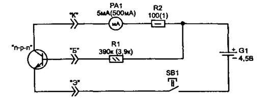
Attention! The transistor must be mounted on a heat sink to avoid overheating. When measuring Npn, the polarity of the power supply will be reversed.
Last edited:
this multi tester is good for transistors with a relatively flat gain curve ..if not, you need equipment that provides more current...i tested BD911 with ebay tesetr - these transistor gain are quite close to each other - as result THD 0,03% @1W.
I also use an old "B&K precision" transistor tester which allows me to push the voltage and current but in current use, the At Mega is going very well
Is this adequate to power transistors? I have multimeters that can measure small and medium transistors but not the output ones. And I'd like to measure gain without buying more tools if possible.
Merci beaucoup!
Attention! The transistor must be mounted on a heat sink to avoid overheating. When measuring Npn, the polarity of the power supply will be reversed.
I can't open link OldDIY.
yes it is 😉Is this adequate to power transistors? I have multimeters that can measure small and medium transistors but not the output ones. And I'd like to measure gain without buying more tools if possible.
Merci beaucoup!

- Home
- Amplifiers
- Solid State
- JLH 10 Watt class A amplifier