I would not recommend using a fan to cool an amplifier for domestic use.
However, you have already gone down this path.
They don't need a lot of power, and a smallish cpacitor or two capacitors and a resistor filter would suffice.
Providing you use screened leads and good earthing on the amplifier, there should not be any interference with the audio, but if you do hear (or see using a scope) some noise a common mode choke (with capacitors on the input and output) on the fan supply should help.
My concern is that you will hear noise directly from the fan. I would not like that in my hifi set up.
What version of the JLH have you built and what size heatsinks are you using?
Is it essential to use a fan - I'd recommend a bigger heatsink by preference.
I would not recommend using a fan to cool an amplifier for domestic use.
However, you have already gone down this path.
They don't need a lot of power, and a smallish cpacitor or two capacitors and a resistor filter would suffice.
Providing you use screened leads and good earthing on the amplifier, there should not be any interference with the audio, but if you do hear (or see using a scope) some noise a common mode choke (with capacitors on the input and output) on the fan supply should help.
My concern is that you will hear noise directly from the fan. I would not like that in my hifi set up.
What version of the JLH have you built and what size heatsinks are you using?
Is it essential to use a fan - I'd recommend a bigger heatsink by preference.
Thank John. The fan is rated to 0.63amps at 12V.
My amp is 1969 - see attached. I hear you about the preference for larger heat sink. It was a combination of things that made me think of doing it this way. One was that my version is quite low powered. I am looking at 19V after filtering into 8 ohm load. I was planning on using Iq 0.95amp which I believe should give about 4W with 18W heat dissipation per channel. Another reason would be that it would be more compact and not have hot parts exposed (young children).
I was planning on using 4 of these:
https://sg.element14.com/fischer-elektronik/sk-48-50-sa-3/heat-sink-for-to-3/dp/4621347
2.8 °C/W. On their own this would seem about 30deg C above ambient for 9W but this assumes equal heat dissipation from all 4 transistors. I'm guessing this would not be the case but hopefully not too much discrepancy??
I would think that this is pushing the limits without a fan but hopefully good laminar airflow vertically up through the heatsinks would tame them enough. Also they are pre-drilled for TO-3 which makes mounting easy. Having them arranged in a circle would also allow for short wires from the boards to each transistor.
The fan is very quiet. Being large it spins much slower than your typical CPU fan.
Any further advice is appreciated.
Attachments

Last edited:
The radiator is small with a thin base. Can be positioned like a well (Common block of 4) - ribs inward and vertically.
The fan blows from below. The cooling effect depends on the flow rate. Try it on the table (on the breadboard).
1. The fan must be powered from a separate power supply.
2. Power wires - twisted pair (better shielded).
3. Three modes - a) does not work at the start (to warm up the radiators faster), b) start at full power for a reliable start,
followed by a decrease in speed at a given heating, c) maximum speed in case of overheating.
4. Switching off the amplifier when overheating.
Last edited:
Compare # 8172.
Thanks, OldDIY!
I'm running several tests with my JLH amplifier.
Reality check
I have built the updated version (more or less) of the circuit. I have a 0-18v 0-18V (300VA) transformer but I am considering wiring single ended so that I only have approx 0-25V dc minus all the voltage drops. I am assuming I can convert the amp back to single supply by connecting the -ve rail to gnd and obviously use an output cap?
The reason for this is to test a lower powered version and see how my relatively small heatsink will cope.
I will use the amp initially in a by-amped setup driving a full range drive unit as a mid tweeter so it has a cap as the first element in the high pass filter.
Hi everyone. Wondering if I can get a little advice for my build. I have finished my amp boards and am looking at the chassis arrangement and power supply.
I am using an old amplifier chassis with perforations underneath and on top. I was thinking of using four separate heatsinks (one for each output transistor) arranged in a circle with a 200mm brushless 12v fan that I have to enhance cooling. I have tested the fan with lesser voltage and it runs right down to about 4V just slower. The fan is quiet when run off a regulated lab power supply.
I have a transformer which puts out 12.15V DC rectified with no load. I was thinking of just putting some decent capacitance across it and running the fan directly. I feel I don't need to be able to control speed of fan given fairly stable heat dissipation of Class A. What do you think? Should I just try something like a good 10000uf cap and if the fan makes no audible noise then go with it?
The mains will be split to power both this transformer and my main transformer powering the amp. A less than perfect psu for the fan won't affect the sound quality from the amp will it?
There are lots of examples of forced air cooling in the Krell KSA 50 pcb thread which was part of the original Krell KSA 50 design.
There are many options with unipolar, bipolar, or floating power supplies. Pay attention to the change of grounding and bias to ensure the modes for DC.
There are some options here. If the heatsinks are arranged in a circle with the fins on the inside it might create a "chimney" effect to give a boosted updraft if there are no obstacles (like a PCB) in the way. But that would be the right configuration for a fan cooled setup.
I suspect that you want the PCB's on the inside, and that probably means you would get a better result with the fins on the outside, if not using the fan.
Another possibility is to mount the transistors directly on the heatsink but then the heatsinks need to be isolated from the chassis and each other, but that would keep the transistor junction temperature down to something like 45 degrees rise, (115W transistor- less for higher power devices) and the heatsink rise as you say about 30 C. The junction temperature is the most important parameter to keep controlled.
As the current and voltages in the JLH are both settable the transistor dissipation should all be the same when the currents and voltages are set to the nominal operating points.
Due to quasi-saturation you will get some increase in distortion just prior to clipping. That usually means increasing the operating voltage and/or current depending on the characteristics of the output transistors.
Temperature rise with fan cooling depends on the air velocity but can be more than halved with modest air flows. Not sure if the datasheet shows that but there are probably many examples as
stal mentioned.
There may be various reasons:
1. Poor quality of capacitors (after long-term storage);
2. High temperature inside the case (no holes, no cooler ...);
3. High-frequency self-excitation (add Zobel, Miller capacitor 20-100 picofarads).
1. Poor quality of capacitors (after long-term storage);
2. High temperature inside the case (no holes, no cooler ...);
3. High-frequency self-excitation (add Zobel, Miller capacitor 20-100 picofarads).
I appreciate your answer OldDiy.
-The capacitors are Nichicon audio rated, 2000 Hrs @ 105°C
and Panasonic FM 7000 Hrs @ 105°C
bought them last year at Digikey
-Amplifier still in unfinished open box until I decide what box use, so that is not.
The third possibility you gave it's out of my league so far 🙂
Manel
-The capacitors are Nichicon audio rated, 2000 Hrs @ 105°C
and Panasonic FM 7000 Hrs @ 105°C
bought them last year at Digikey
-Amplifier still in unfinished open box until I decide what box use, so that is not.
The third possibility you gave it's out of my league so far 🙂
Manel
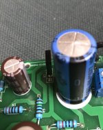
Yes, check to make sure that the polarity is not reversed on that output capacitor. I can't quite tell from your photo but I wonder if the capacitor is installed backwards.
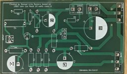
Perhaps post a larger photo (of the full PCB) and also let us know if you are using NPN outputs or if this is one of the PNP JLH kits.
If you have the schematic for your board or kit then post that too along with the full photo.
Perhaps post a larger photo (of the full PCB) and also let us know if you are using NPN outputs or if this is one of the PNP JLH kits.
If you have the schematic for your board or kit then post that too along with the full photo.
Correct polarity of electrolytic capacitors and load connections?
You are right! Thanks a lot for troubleshooting. I wonder if is going to sound even better after I correct output capacitor.
Manel
Yes, check to make sure that the polarity is not reversed on that output capacitor. I can't quite tell from your photo but I wonder if the capacitor is installed backwards.
Perhaps post a larger photo (of the full PCB) and also let us know if you are using NPN outputs or if this is one of the PNP JLH kits.
If you have the schematic for your board or kit then post that too along with the full photo.
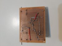
The output capacitor is definitely backwards, and the name of John Linsley Hood is misspelled. So embarrassing since I designed the board.
Thanks for chiming in.
Manel
Attachments
Ok. I could not quite tell with the first photo but it did look like a resistor went to the negative terminal of the output blocking capacitor in the photo which would be backwards. (For NPN version.)
Happy to hear it is working.
Happy to hear it is working.
Good eye! and is interesting that was sounding quite good!!!
I'll try it with the corrected position tomorrow.
Thanks again
I'll try it with the corrected position tomorrow.
Thanks again
Last edited:
I'm thinking about using cap multiplier for ripple attenuation. I want to minimise voltage drop. Will I need to also regulate it for JLH69?
There are some options here. If the heatsinks are arranged in a circle with the fins on the inside it might create a "chimney" effect to give a boosted updraft if there are no obstacles (like a PCB) in the way. But that would be the right configuration for a fan cooled setup.
I suspect that you want the PCB's on the inside, and that probably means you would get a better result with the fins on the outside, if not using the fan.
Another possibility is to mount the transistors directly on the heatsink but then the heatsinks need to be isolated from the chassis and each other, but that would keep the transistor junction temperature down to something like 45 degrees rise, (115W transistor- less for higher power devices) and the heatsink rise as you say about 30 C. The junction temperature is the most important parameter to keep controlled.
As the current and voltages in the JLH are both settable the transistor dissipation should all be the same when the currents and voltages are set to the nominal operating points.
Due to quasi-saturation you will get some increase in distortion just prior to clipping. That usually means increasing the operating voltage and/or current depending on the characteristics of the output transistors.
Temperature rise with fan cooling depends on the air velocity but can be more than halved with modest air flows. Not sure if the datasheet shows that but there are probably many examples as
stal mentioned.
Thanks John. I've ordered the heatsinks so will try the options you mentioned. The fan worked fine with just rectification and a 3300uf cap. It did pull the 12.6VDC rectified under no load to 7.6V under load but the fan still had reasonable speed and was very quiet - seemingly no issues with the lower voltage. I'll try like that for simplicity to start. Other option I had considered is the chimney idea of yours with the amp boards inside mounted vertically to limit the blockage to airflow.
- Home
- Amplifiers
- Solid State
- JLH 10 Watt class A amplifier