The 25mA limit was the reason for limiting each section to less than 25mA. And, as we only needed up to 75mA that was ok. The resolution is approx. 2mA with my resistor selection.
I assume the current rating is for each switch, not total?
If it is per contact, that would be more than enough. (Even if total, it is still adequate).
It's a question whether it would be cheaper, with the 8 resistors, than a 2.5W pot. (probably).
I assume the current rating is for each switch, not total?
If it is per contact, that would be more than enough. (Even if total, it is still adequate).
It's a question whether it would be cheaper, with the 8 resistors, than a 2.5W pot. (probably).
Last edited:
hello what is the diagram of # 6418 for and how to insert it in the jlh diagram the translations are incomprehensible thank you
hello what is the diagram of # 6418 for and how to insert it in the jlh diagram the translations are incomprehensible thank you
Many will understand it.
he be thank you c is nice as an answer it answers my question perfectly ..... in clear tanpis for beginners here we discuss between connoisseurs thank you
What I found in my earlier tests, is that it can be useful to tune both R1 and R2 (ref original schematic) to optimize the current sharing between the output transistors. This will have effect on the distortion, and maximum output current vs idle current.
Just fiddling around with these can make big changes in distortion. Finding the optimum idle current for the output transistors, and then balancing the two resistors for the lowest distortion or desired distortion harmonic profile.
Another note to prasi when making the PCB: make room for big capacitors, the original values are too small IMHO (C1, C2, C3 and input cap). Values x10 or more..
big caps are 35mm dia, middle sizes are 20mm dia and smaller ones are 13mm dia. that should give plenty of options. I will also add pitch options in the final stages.
1. Input cap is big enough for folks? 37.5mm pitch 20 mm wide.
2. what will happen if we make C8 bigger say 2200uF or even 4700 uF
regards
prasi
This is what i had posted long ago. now not possible to change without changing entire layout. bailing out...

he be thank you c is nice as an answer it answers my question perfectly ..... in clear tanpis for beginners here we discuss between connoisseurs thank you
The JLH is interesting to anyone. We people hiding from the nasty things like Corona virus have discovered that the JLH is quite complex and worthy of much thought. Not complex to make or improve. Very complex to understand it's exact working. I will be honest, I perhaps understand 70% of it.
People have been exploring better transistors in their working JLH. I thought using unseen input B could be a larger difference. As a preamp is required why not make it work in an unusual way. A thousand questions come from this. A brilliant distraction that certainly doesn't exclude a beginner. I don't think anyone here is a connoisseur. John must get close in the true meaning of the word.
If you pursue how negative feedback works you won't be wasting your time.
Many of us don't buy the kits. JLH is a rare example of a world class design that can be made point to point or on strip board. That's impossible to believe but true.
good evening nigel I would like to know if you connect the output of the preamp between c3 and the mass and the values of the input resistors. the problem I am having with my amp, often the signal from some sources has too weak an output signal so I lack power
At first use it as standard 220R. Do not change the 2k7 as it sets the DC conditions controlling the mid voltage. However try a gain change first before anything esoteric. Higher gain tends to be more stable also!!! If hum is ok often it is a positive experience to do this.
You could try 110R by adding another 220R in parallel. By doubling the gain you will double the distortion. Now the big surprise. You might like that as it's very nice distortion like a high grade tape recorder. I am listening to FM radio. It is higher in distortion than this modification. It sounds wonderful. This means no removing the existing resistor.
No need to feed into input B. I hoped it would cause a discussion.
To answer another question. 4700 uF output capacitor should be very good. My Armstrong 625 has that.
Perhaps the answer is to measure the gain of your output devices and select a resistor based on that. Here is a circuit which runs from a 5V power supply (old computer one perhaps) and sets the current to approx. 3A (adjustable with the emitter resistor).
Purpose of the additional PNP transistor is to allow the NPN to run at a more constant current without too much effect on the output transistor current.
Not shown, but an ammeter should be wired in series with the base of the OPT.
Not tested- just a proposal.
If I understand correctly , this circuit is to check actual hfe of output transistors. So my questions are where to measure, and what resistor value to be changed according to the readings.
Thanks.
Member
Joined 2009
Paid Member
I just found some 2n3055 in some old power supplies that I can scrounge. They should be better than the 2n3055H devices in my current amp on account of having a much better ft. I believe folk are still v happy with their 2n3055 based amps and all of you haven’t felt the need to upgrade to even faster devices?
The need for speed in class AB is often assumed to apply to class A too. Well, it doesn't but the matter was discussed recently and the actual benefit is said to be only in the greatly improved linearity that also comes in most modern audio power devices.
Theoretically, feedback should be able to cope with providing class A linearity but I assume because of the JLH's simplicity, it needs all the help it can get if you want everything from just four transistors that could require dozens in designs where cost and complexity are no object.
As I've heard fantastically good sound from JLH amps with no such frills, I don't go along with misunderstandings or happenstance regarding class A v AB operation nor a need for high Ft power transistors. If you want better current linearity, no problem with Onsemi's MJL21194 or its pnp variant. For interest, I've also successfully tried KEC's KSD1047 which is a cheap, intermediate 15MHz type in TO3P format. It seems to have a good compromise spec. but there may be more genuine, useful types for class A out there too.
It turns out that 30 MHz audio power transistors are now cheaper than standard 4MHz transistors so I guess it is reasonable to want to use them, provided you are certain of the stability of the complete amplifier. Stability isn't guaranteed just by design and board components or making guesses, though. You will probably need to measure and check with a 'scope to be certain of the result but that could easily wipe out any savings on parts.
Hello Prasi
Sorry this is a bit late, but I'm wondering about the physical dissipation in the preset pot R13. It needs to be able to handle the highest current possible, which may mean using a larger one than a 10mm(is that right?) pot.
The circuit diagram shows 4 transistors in the power amplifier section. There are 5 on the pcb which shows a change to the alternative output current adjustment mentioned in JLH's article in December 1970 and continued on into the 1996 update.
This gets around any potential problems from inductance in a wire-wound pot in the boot-strap arrangement plus the cost factor and bulk of such a component, and perhaps the work involved in a re-work of the pcb layout.
I would leave the extra stability networks added following the publication of the first article. These can be added if there are problems with stability due to proximity of input and output wires.
The connection of C10 between the collector of the split phase drive transistor and the emitter of the input transistor is a scheme JLH used for frequency compensation in his later designs including those using MOSFET power devices.
There is a good reason why he did this rather than use a lead capacitor in the feedback return.
hello nigel I am sorry between my little knowledge in electronics and the translations which are very very bad I do not understand anything to your explanations could you make me a drawing of the location of the preamp on the existing diagram of the jlh thank you
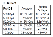
manel - here is the test circuit with the ammeter added. The current should be set to 100mA if you don't have an autoranging meter.
This determines the base current needed for the transistor to pass 3A (this current can be checked by measuring the voltage across the emitter resistor).
The base current is therefore needed in the circuit to drive the upper output transistor at full current. That is set by R1 and R2 (plus any other series resistor like R12 in Prasi's diagram).
You need to add a small margin so that the driver transistor does not cut off completely.
That would be something like 10-15% extra, but any increase has a direct impact in output dissipation, and standing current, of course.
In Prasi's circuit if the base current of the MJL21194 is 50mA, say, then adding 10% means 55mA in the resistors. The supply voltage is 24V so the voltage across the resistors is half this, less a Vbe of the upper output transistor, or about 11.4V.
That makes the resistances needed total 11.4/55mA=207 ohms. These can be split 50:50 but reducing R1 generally helps. In Prasi's circuit R1 is 47 ohms, and R2+R12 is the remainer at 160 ohms, though probably the 10 ohm is not really necessary - but the output stage current will increase a little if omitted.
Attachments
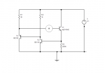
And the burden voltage of the ammeter nicely increases the collector-to-base bias voltage of Tr2.
I have a couple of comments on mjona's observations.
First, I do not think an inductive component will have any significant impact when in the position of R2-R12 - these are supposed to be a constant current source, and if anything, an inductance will help to increase the impedance and make a better current source.
I have not simulated this - I may be wrong, but with a high series resistance, (note this caveat) any inductance in a wire wound pot is unlikely to be a problem, but may actually be an advantage. A possible downside might be that a protective diode should be added to prevent damage in extreme circumstances (clipping).
Secondly, while I agree that JLH's modification using a transistor pair instead of resistors does allow the use of a low power pot, it detracts a little from his original concept in that a bootstrap circuit, though considered old fashioned now, provides a higher output voltage and can drive the upper transistor to its Vce(sat) value instead of being limited to about a volt or so below the rail (plus a Vbe drop), so if only from that point of view requires a higher power supply voltage and affords lower efficiency than his original. This is not to criticise the idea of using a CCS - most Class A builders won't really care for a slight increase in power, I suspect, but I do think the original circuit is more elegant.
The main problem with using a pot (without padding resistors) is that it will be large; it will probably be wire wound; and certainly not cheap these days.
If I were to build a JLH again I'd probably measure the device gain and use a fixed resistor as appropriate, as Nigel and Ian have mentioned. In a production environment it might be as easy to use a medium power pot just to test the setting needed - using test pins - and solder in the nearest resistor to that value, especially as it would need to be a 1W part.
I agree that pots always seem to lose performance after a few years, so I agree with the recommendations for a fixed resistor, and that is my preference over a CCS - for this particular circuit at least.
mark -
yes, it does. If readers (I doubt you would), like me, use a trusty Avo for perhaps 90% of measurements (going down though) it would be increased by about 200-300mV.
yes, it does. If readers (I doubt you would), like me, use a trusty Avo for perhaps 90% of measurements (going down though) it would be increased by about 200-300mV.
I suspect in normal use the constant current working of a JLH could make it set and forget.
I have two AVO. Like slide rules I find them a bit hard to use compared with modern devices now.
I bought a Peak LCR 45 component tester about six months ago. Initially thinking it overpriced and badly made I have changed my mind. I measured a choke at 12 mH and 0.05R. In reality 0.035R using a constant current of 2.5A. Seeing that the LCR was clamped to the solder that's impressive. It gave the ban the bomb Audax tweeter of cheaper speakers as 5R 19 uH. It gets very close to the best measurements I can make. It's presentation is poor.
I will draw for our less experienced builders how to set gain. It's a ten minute test which can be reversed in ten minutes. I will give the pros and cons.
- Home
- Amplifiers
- Solid State
- JLH 10 Watt class A amplifier