If the current temperature coefficient is negative (e.g. the bias current goes down when temperature goes up) then I would not add a second diode. Use a (to start with) 100 ohm potentiometer and see what happens (if not to much use a 500 ohm one).
Where exactly ?
Where exactly ?
In series with the existing (trans)diode (where you would add the 'extra' diode).
I was planning to add two extra transdiodes to keep the circuit simetry... the output from the opamp feeds the "middle" of the transdiode arrangement, so I do not really get where should I place the trimmer..... or do I need two trimmers ?
Please bear my lack of knowledge... I am eager to understand the concept and will surely comply if you have the time to act as a "regular" teacher 🙂
Please bear my lack of knowledge... I am eager to understand the concept and will surely comply if you have the time to act as a "regular" teacher 🙂
Still have an interesting problem. There are two different pinouts for the BF246A floating around on the datasheets.
Can anyone tell me if A or B is the correct one?
The one is 'top'-side and the other 'bottom'-side? It should be GSD 123. But I'm a bit late 🙂
The one is 'top'-side and the other 'bottom'-side? It should be GSD 123. But I'm a bit late 🙂
Yes I see 🙁 Joachim had the correct answer 🙂
I was planning to add two extra transdiodes to keep the circuit simetry... the output from the opamp feeds the "middle" of the transdiode arrangement, so I do not really get where should I place the trimmer..... or do I need two trimmers ?
Please bear my lack of knowledge... I am eager to understand the concept and will surely comply if you have the time to act as a "regular" teacher 🙂
For what I can find, the bias generator is floating (or point me to the correct schema) if so (it is floating), then no problem just add the pot in series with the diodes. If not, then do it any way 🙂 the servo will catch it, the symmetry is only broken by R/OLG (and that should be a very tiny number).
But point me to the schema/post you are building.
That should be 'about' R/(OLG/CLG) (and that should be a small number) (but larger than tiny 🙂)
I did not test the Muses yet but i have some and i will.
No Patrick, i did not get your mail. I do not know why.
No Patrick, i did not get your mail. I do not know why.
For what I can find, the bias generator is floating (or point me to the correct schema) if so (it is floating), then no problem just add the pot in series with the diodes. If not, then do it any way 🙂 the servo will catch it, the symmetry is only broken by R/OLG (and that should be a very tiny number).
But point me to the schema/post you are building.
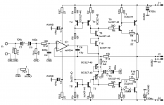
Here it is:
There are differences but only regarding the opamp psu (317 337)
if I understand correctly, the transdiodes create a 4 x Vbe voltage difference between the output drivers bases.... if I introduce a resistor, there will be more voltage difference caused by Vdrop on the resistor, dependent on the current passing on the transdiodes... right ?
I am not sure where to place the trimmer to keep the signal path symmetry.
Attachments
I think the 14mA you get is just right. As i told you the CFB output stage does not need much idle for optimum performance.
Yes, a resistor in series with the transdiodes gives a voltage drop that increses the idle.
You could try two 100 Ohm resistors before the emitters of T10, T11.
That way you maintain the symmetry. You can also put that resistors between the transdodes or at the far end of T9, T12. That will not make much of a difference.
Thank you, now it is completely clear 🙂
If temp rises, (due to my bench powerfull light), idle goes down to 11mA.... I will test the rig after it is properly enclosed and see what happens,,,, if the idle gets near 15mA I will let it as is.
If temp rises, (due to my bench powerfull light), idle goes down to 11mA.... I will test the rig after it is properly enclosed and see what happens,,,, if the idle gets near 15mA I will let it as is.
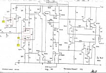
Here it is:
There are differences but only regarding the opamp psu (317 337)
if I understand correctly, the transdiodes create a 4 x Vbe voltage difference between the output drivers bases.... if I introduce a resistor, there will be more voltage difference caused by Vdrop on the resistor, dependent on the current passing on the transdiodes... right ?
I am not sure where to place the trimmer to keep the signal path symmetry.
Just place it in the E of T10, then when you have set a value; replace it by 2 fixed resistors (one in E T10 and one in E T11).
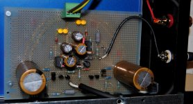
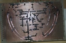
Finally got the time to finish this build and am actually listening to it 🙂
Too soon to really comment but specially pleased with the good spatial presentation.
Bass is full and highs are cristal clear without being too frontal.
It worked right away without any glitches.
I will let it settle for a while and report latter this week with pics and full listening impressions.
Too soon to really comment but specially pleased with the good spatial presentation.
Bass is full and highs are cristal clear without being too frontal.
It worked right away without any glitches.
I will let it settle for a while and report latter this week with pics and full listening impressions.
I am very happy that it works right away. Good job.
I build both, a single ended and a balanced version. Yes, i think it is pretty good, especially considering the simplicity.
I look forward to your impressions about the sound.
I build both, a single ended and a balanced version. Yes, i think it is pretty good, especially considering the simplicity.
I look forward to your impressions about the sound.
I had a long listening period and now have a clear idea how it sounds.
Bass goes really deep with good slam and a tight presentation.
Imaging is quite good enabling a wide soundstage with acceptable depth.
Trebble is extended but slightly stark.... midrange seems slightly recessed IMO.
It is quite agreable to listen to, not producing fatigue but lacks the emotional fluidity of my bigger amp.
I would like a more fluid presentation so I would like to increase iddle ..... how much far can I go ?
Can i use two 200r résistors in series with the transdiodes ?
Attachments

- Status
- Not open for further replies.
- Home
- Source & Line
- Analogue Source
- JG´s Nobrainer and Nobrainer Discrete