On topic:
Whew, where was I?
I tried Choky's probe ideas:
Input seems to be 0.008v
Output seems to be 0.1v
gain: 12.5
That's much better!
Whew, where was I?
I tried Choky's probe ideas:
Input seems to be 0.008v
Output seems to be 0.1v
gain: 12.5
That's much better!
Zen Mod said:
I'm your Nanny
Magura is pooftah ......... ( I hope his Missus doesn't read this thread )

I saw that !!!!!

Magura

Magura said:
I saw that !!!!!
Magura
There, there...everything's going to be ok...
tell me all about your chokes and what you want to do Zen Mod. 😀 😉 😀
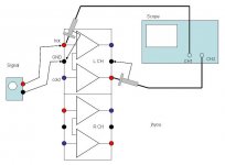
I usually measure Vi and Vo as shown for unbalanced-in and balanced-out at different frequencies:
V gain = Vo/Vi x 2
Then, I could reasonably estimate what is the V-gain at each frequency
and how the gain curve varies along the frequency axis.

Hmm . . . the forum refuses attachement of my sketch having size of 37kB. Why . . . ? Because there are too many OTs?
V gain = Vo/Vi x 2
Then, I could reasonably estimate what is the V-gain at each frequency
and how the gain curve varies along the frequency axis.
Hmm . . . the forum refuses attachement of my sketch having size of 37kB. Why . . . ? Because there are too many OTs?
Babowana said:I usually measure Vi and Vo as shown for unbalanced-in and balanced-out at different frequencies:
V gain = Vo/Vi x 2
Then, I could reasonably estimate what is the V-gain at each frequency
and how the gain curve varies along the frequency axis.
Hmm . . . the forum refuses attachment of my sketch having size of 37kB. Why . . . ? Because there are too many OTs?
I've noticed that PNG graphics can be physically larger than the other formats. Try that.
What if you have balanced in and single-ended out?
I tried to attach my sketches in different ways, but in vain.
I will retry later at night . . . hoping ok then.
I will retry later at night . . . hoping ok then.
At least... it works.
Thx for this very nice sketch.
All this details about testing procedure, (even where placing probes, where not, etc).. are very usefull for people like me,
since I never managed to use properly my recently ebayed scope...
It will encourage me to give other try
Manu
Thx for this very nice sketch.
All this details about testing procedure, (even where placing probes, where not, etc).. are very usefull for people like me,
since I never managed to use properly my recently ebayed scope...
It will encourage me to give other try
Manu

Babowana said:
It does not matter of unbalance-in or balanced-in.
It makes a huge difference, with my system, where I place the input probes. The input voltage is double when I probe the + and - inputs together verses + and ground.
I'm not happy with the fact my x-over's minus output has twice the voltage of the positive output.
I couldn't figure out how my little gain-stage could put out so little voltage. It just didn't make sense. So, I connected my VOM to my gain-stage. I set the VOM reading to AC since the gain-stage was receiving a 1000hz signal:
input: 0.375v
output: 7.8v
My scope reads increments differently than I thought; each little mark means a division, not just the large grid lines. It doesn't even seem to matter that the probe is 10x, it still matches the VOM. A bit confusing......
My gain is high: 20.8
BTW, the gain-stage begins to clip when I ask it to deliver more than 7.8 volts.
Does it seem that I'm on the correct path, or have I deluded myself? 😀
Wouldn't be the first time.......
Edit: I connected my VOM just like the last pic I submitted, using Babowana's drawing.
carpenter said:It makes a huge difference, with my system, where I place the input probes. The input voltage is double when I probe the + and - inputs together verses + and ground.
We are going to check V-gain.
It doesn't matter whether we use balanced or unbalanced input.
The unbalanced output devided by the input (balanced or
unbalanced) gives us the v-gain.
Hope you will check also at lower frequencies . . .
I don't own a signal generator that works; my old heathkit has lost a marble or two. I'm using a cd with a 1000hz tone for now.
As per my last post, does my measuring process seem correct with the volt/ohm meter?
As per my last post, does my measuring process seem correct with the volt/ohm meter?
carpenter said:As per my last post, does my measuring process seem correct
with the volt/ohm meter?
I guess your scope has eight divisions vertically.
Just adjust for both channels to have the same volts/div setting.
And, trust the results coming from the equipment.
For example, If the volts/div setting is 5 volts,
then each of the eight vertical divisions represents 5 volts.
Meanwhile, if you use different v/d settings between two channels,
then put out your HP calculator to practice math with
the different scaling factors.
Oh . . . I’m assuming that you set the both probes to 10X.
Otherwise, you need another practice of the math with
the different scaling factors.
carpenter said:I don't own a signal generator that works; my old heathkit has lost a marble or two. I'm using a cd with a 1000hz tone for now.
Suggestion: buy a Leader LAG120B (be careful 120B, not 120A) for 50 bucks on ebay. It's very good and compact, trust me.
massimo said:
Suggestion: buy a Leader LAG120B (be careful 120B, not 120A) for 50 bucks on ebay. It's very good and compact, trust me.
Thanks, I'll do that!😀
Edit: Hummm, none available......bummer.
Babowana said:Steal one from your friend, after making him hell o drunk . . .
Actually, the only friends I have that love audio are the people on this forum.......
Hey bud, what to have a cyber-drink with me?


- Home
- Amplifiers
- Pass Labs
- JfetBOZ mods