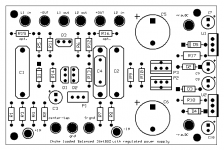
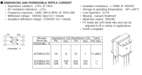
Does anybody have an idea to share about how to calculate the optimum inductor characteristics?
On the positive side, I do have a distortion analyzer so I can do the adjustment Nelson recommends.
On the positive side, I do have a distortion analyzer so I can do the adjustment Nelson recommends.
I don't know how to calculate size, so I'm going to experiment with various sizes of inductors. Mouser has inductors with various Henries for 2 buck apiece. I'll be trying several sizes and won't have to worry about breaking the bank in the process.🙂
Carpenter... Iam pretty sure crazy Magura can help you out here... If he just see this... I am interessted in howto calculate size/windings of inductor, and how the windings should be done...
One thing i must say, that even how the inductors are made, you really should get them glued/(donno what the name is in english hope you understand... The inductor is lowered into some liquid and then in 120degree oven for about 8hrs.) together, for avoiding that the Cu will vibrate 😀...
Jesper.
One thing i must say, that even how the inductors are made, you really should get them glued/(donno what the name is in english hope you understand... The inductor is lowered into some liquid and then in 120degree oven for about 8hrs.) together, for avoiding that the Cu will vibrate 😀...
Jesper.
Hi Jesper,
The inductors in this little gain-stage are passing such small amounts of current that I don't think the winding will be vibrating. Never the less, the Mouser inductors I spoke of are small, commercial units, and probably already dipped in the proper resins.
It was very nice of you to suggest that Magura could possibly help me out. Unfortunately, I'm sure he's a very crazy, er, I mean BUSY man--not to mention, he probably has his own diy projects to worry about.
Thanks for taking the time to share your thoughts.🙂
lykkedk said:
One thing i must say, that even how the inductors are made, you really should get them glued/(donno what the name is in english hope you understand... The inductor is lowered into some liquid and then in 120degree oven for about 8hrs.) together, for avoiding that the Cu will vibrate 😀...
Jesper.
That's dielectric varnish; you dip the trafo, coil or choke on it for 10 or 15 min or even more time to let the trap air escape. Idealy you should apply a vacumm to the can containing the varnish/trafo to help trap air to escape.
There are two types of varnish, air dry or oven dry, so take your pick.
I do them by leaving the trafos on the dip for 30 min, lift them over the can to drip for another 30 min and use no vacumm using air dry varnish which I buy by the gallon. You can use them 24/48 hours later depending on ambient temp.
Now, if you want to go further just heat the trafo/coil to some 50/80ºC over a heater or oven before dipping, this will eliminate most of the humidity in the part and let the varnish run easy inside the coil.
Hope this helps 🙂
Dielectric varnish which I buy from the motor rebobin supplier stores locally which they also sell fish paper and copper magnet wire.
Dont know if you have such suppliers in the US.
Dont know if you have such suppliers in the US.
apassgear said:Dielectric varnish which I buy from the motor rebobin supplier stores locally which they also sell fish paper and copper magnet wire.
Dont know if you have such suppliers in the US.
I'll try "rebobbin supplier stores" in the search engine and see what happens. Who knows, I might get lucky.
Thank-you, Tony.
They're supposed to arrive this Friday. With any luck, they'll work and I can button up my F4 project.
What an interesting day and age in which to live. Five years ago, I wouldn't have dreamed of using software and the Internet in the designing and ordering of pcbs--it's a very cool aspect to this generation. I wish I would have known about this stuff when the Aleph-X was on the table.
I guess the best part of this process is that with the help of this forum and the highly intelligent contributions of upper-class type brains, I can finally create something of my own.🙂
Thank-you, everyone!
I'll try "rebobbin supplier stores" in the search engine and see what happens. Who knows, I might get lucky.
McMaster has electrical insulating varnish, just in case 'rebobbinn supplier stores' doesn't pan out.
(did I mention, McMaster has everything?)
JJ
I don't know how to calculate size, so I'm going to experiment with various sizes of inductors. Mouser has inductors with various Henries for 2 buck apiece. I'll be trying several sizes and won't have to worry about breaking the bank in the process.
Well, let us know what you come up with -- I may have to try choke loading my BZLS.
I didn't read the above posts real close, I think you want potting compound for your inductors. I think McMaster has that too.
JJ
I connected the scope today:
My gain stage is receiving a balanced input signal. I measured from one input with my scope.
I measured with leads that have 10x mag. I placed the scope on 0.1 volts/div. I offered the gain-stage a 1000hz signal that filled the space of one division--peak to peak (receiver knob is in a very quiet setting: 50db down). I then relocated the leads to the gain-stage output. Its peak to peak reads three division spaces.
Is this a gain of three?
Edit: I measure the output of the F4--it measured the same as the output of the gain-stage. Naturally.
carpenter said:.........
Is this a gain of three?
............
naah..........
it's gain of three divisions .

I wasn't certain if the gain was three because of the balanced input--I was only measuring from one input. Are you supposed to sum the inputs before computing the gain?
I presume that you have overall gain of six (divisions 😉 ) but - that really depends - is it minus leg of output grounded or not ;
so - to be sure - try to measure again - balanced input-balanced out etc ;all possible combinations you can think
then you'll see with own eyes , and nobody must tell you what you can see ..........
so - to be sure - try to measure again - balanced input-balanced out etc ;all possible combinations you can think
then you'll see with own eyes , and nobody must tell you what you can see ..........
- Home
- Amplifiers
- Pass Labs
- JfetBOZ mods

