Babowana said:I will not take it seriously in case of John's circuit.

Why not?
Magura 🙂
It is considered necessary when the different thermal tracking
does affect the output dc offset and its drift. But, John's
circuit is safe from such problem with output coupling caps.
does affect the output dc offset and its drift. But, John's
circuit is safe from such problem with output coupling caps.
Babowana said:It is considered necessary when the different thermal tracking
does affect the output dc offset and its drift. But, John's
circuit is safe from such problem with output coupling caps.
If this is the case, it sure makes it easier to keep the pcb traces looking tidy. I rerouted the pcb to allow thermal contact of the jfets and, let-me-tell-you, what a pile of snakes!😀 I made it work, but oh it ugly....

carpenter said:If this is the case, it sure makes it easier to keep the pcb traces looking tidy.
Sure it is.
The coupling is not harmful at all, tho . . .
John, May ask a few questions? and give you a few ideas to think about?
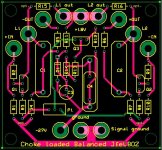
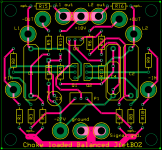
Your input connections are right next to your output connections. That is generally not a good idea. Try to give them and any traces they connect to more seperation.
C1 + C2 would be huge capacitors in reality, 10uF Films??? That footprint does not look big enough.
It looks like you have included R15 + R16 as optional R loads for those who don't like the L Loaded idea??? Good...
On the schematic, R12 at the -In is R10 on the layout??? Otherwise there are 2 R12s??? Maybe it's the res of the pic???
Speaking of Rs, R3 and R8 optional??? Also, It is always a good idea to "bypass" a pot with some R in the case the pot opens up or has intermitant contact while adjusting. It will make big transients in your system, amongst other things, if this happens.
I would use + and - 18V rather than the -27??? (Hmmm, 4 - 9V batteries?)
Hey, I might just want to help you reduce your cost on these boards too. I'm good for a few... lookin good...
BTW Happy New Year All 😀 😀 😀
Thanks flg.
I'll implement the mods you suggested.
I believe that the footprints on the caps are 8/10 of an inch. This pretty much fits the Panasonic film caps. I'll double check that too.
I'm not running R3 and 8 in my breadboard experiment, but wanted to allow for them on the pcb--to opt out would simply mean using a jumper. I happen to have 20 ohm pots and didn't want to order 10 ohm. Your protection idea makes sense; I'll be ordering 10 ohm pots and 5 ohm resistors.
You hit the nail on the head with my addition of R15 and R16.
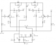
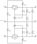
I'm including the most current set of schematics that the pcb is linked to.
Perhaps less negative voltage is OK, I just wanted to make certain that the bottom rail was sufficient. I'm using three 9volt batteries on that section. 18-0-18 volt power supplies are easier to find. I'll disconnect one of the batteries and listen.
It would be nice to have some help with the pcb cost, thanks.
Happy New Year!
I'll implement the mods you suggested.
I believe that the footprints on the caps are 8/10 of an inch. This pretty much fits the Panasonic film caps. I'll double check that too.
I'm not running R3 and 8 in my breadboard experiment, but wanted to allow for them on the pcb--to opt out would simply mean using a jumper. I happen to have 20 ohm pots and didn't want to order 10 ohm. Your protection idea makes sense; I'll be ordering 10 ohm pots and 5 ohm resistors.
You hit the nail on the head with my addition of R15 and R16.
I'm including the most current set of schematics that the pcb is linked to.
Perhaps less negative voltage is OK, I just wanted to make certain that the bottom rail was sufficient. I'm using three 9volt batteries on that section. 18-0-18 volt power supplies are easier to find. I'll disconnect one of the batteries and listen.
It would be nice to have some help with the pcb cost, thanks.
Happy New Year!
Attachments
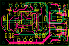
Wow! That has become quite a busy board in a hurry. Very nice. What is the needed voltage on the input side?
DaveM said:Wow! That has become quite a busy board in a hurry. Very nice. What is the needed voltage on the input side?
Thanks for the compliment, Dave!😀
To be quite honest, I'm hoping to use the voltage source that the F4 employs. The regulator is adjustable, so I can dial in whatever voltage sounds best for the jfet combo.🙂
carpenter said:To be quite honest, I'm hoping to use the voltage source that the F4 employs.
Yeah . . . then we could build a nice Class A int. amp in one box,
couldn't we . . . ?
Babowana said:
Yeah . . . then we could build a nice Class A int. amp in one box,
couldn't we . . . ?
Ooooh....
But, really, we'd need a pumpkin, or some other preamp to get us up to proper levels. My little gain stage is just that, and only that. It sure sounds good, though. When used with my receiver, it makes the F4 shine without pushing the volume control through the roof.🙂
carpenter said:Ooooh....
My little gain stage is just that, and only that. It sure sounds good, though.
🙂
I believe that you are enjoying the nice sound from your 100dB-speakers at the sweet first watt level. By the way, when I saw your Jfet-bosoz first time, I thought that it was a simple circuit and could become a nice combo with my F4 (+/-12.5V rails) to shape an int. amp. For this, of course, I should replace the choke load with R-load for more gain because of my low efficient 85dB-speakers. And, I would vote the Jfet-CCS for mine.
Ah . . . at last, I could open my shipment in this week. For the moment, I am just going to set up my music system with tube-pre/ F4/ ATC SCM7 until I could give a try to your Jfet-bosoz . . . hopefully with my free time . . .
I am very interested in the evolution of your Jfet-bosoz.
Well, presently I am running a single F4 with a pair of 96 db efficient speakers. The second F4 is on the bench awaiting mounting the the heatsinks and final wiring. I am not sure how much gain I will really need once I have 2 monoblocks, but with the J-BOZ in there now I start getting distortion at about the max end of comfortable listening.
What do you think would I have enough gain with your circuit?
What do you think would I have enough gain with your circuit?
- Home
- Amplifiers
- Pass Labs
- JfetBOZ mods