Ok, so I'm trying to understand how to use my scope. I turned up the volume on my receiver, which is sending the 1000hz signal via the CD player.
My scope's test leads are 10x and the scope is set at 0.1volts/div. This means that each division is 0.01volts. Correct me if I'm wrong...anybody!
To the best of my knowledge:
I have 0.015 volts to the gain-stage.
This was measured on the balanced lead that's connected to the inverting transistor which feeds the F4. Incidentally, the balanced lead feeding the non-inverting transistor is reading about twice the voltage of the inverting side.
I have 0.27 volts out of the gain stage.
So, 0.27 divided by 0.015 = 18
This is the gain?
Edit: I ran the receiver at 25db down (the volume I listen to the home theater--very loud!) and had no clipping. This is also the volume used when I sampled the above readings.
puting yor probe in 10x means that you are attenuating input by factor 10;
always leave probe in "1" ie . not "10x" if you can ;
so - please confirm few things :
-you are running input of little stage in balanced mode ?
-you are using inverted (-) leg on output - to F4 , using it unbalanced , but without grounding + leg ?
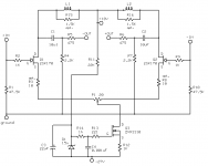
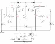
find enclosed your (I hope I found it) last - valid schematic , and give us few words with exact schematic, maybe even with few dots to help us understand your measuring
if you have gain of 18x ( ie. ~25db) it's not for surprise ...... you are running it open loop, with miniscule amount of feedback .
I'll do - in your boots - one of two things :
1. try source degeneration
2. try to make it as susy stage
then - decide what's better for your ears
always leave probe in "1" ie . not "10x" if you can ;
so - please confirm few things :
-you are running input of little stage in balanced mode ?
-you are using inverted (-) leg on output - to F4 , using it unbalanced , but without grounding + leg ?
find enclosed your (I hope I found it) last - valid schematic , and give us few words with exact schematic, maybe even with few dots to help us understand your measuring
if you have gain of 18x ( ie. ~25db) it's not for surprise ...... you are running it open loop, with miniscule amount of feedback .
I'll do - in your boots - one of two things :
1. try source degeneration
2. try to make it as susy stage
then - decide what's better for your ears
Attachments
inductor
The choke you ordered and transformer you used must have iron core. Iron core has losses at high frequencies. and it increase with frequency.
So, I think it is better to use ferrite core, and it can improve the high frequency response somewhat.😀
The choke you ordered and transformer you used must have iron core. Iron core has losses at high frequencies. and it increase with frequency.
So, I think it is better to use ferrite core, and it can improve the high frequency response somewhat.😀
Re: inductor
Say after me: bifilar air core inductors.
(Just ask Steenoe if in doubt)
Magura 🙂
jkchoi said:The choke you ordered and transformer you used must have iron core. Iron core has losses at high frequencies. and it increase with frequency.
So, I think it is better to use ferrite core, and it can improve the high frequency response somewhat.😀
Say after me: bifilar air core inductors.
(Just ask Steenoe if in doubt)
Magura 🙂
Zen Mod said:puting yor probe in 10x means that you are attenuating input by factor 10;
always leave probe in "1" ie . not "10x" if you can ;
so - please confirm few things :
-you are running input of little stage in balanced mode ?
-you are using inverted (-) leg on output - to F4 , using it unbalanced , but without grounding + leg ?
The test leads are 10x, not the scope. I'm stuck with them until I purchase new leads.
The answer is "yes" to your other questions.
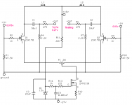
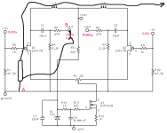
Here's the schematics with voltage values that I'm currently using:
Attachments
Zen Mod said:woodie - there it is - sorta susy

Sure, I like to play with Susy! 😉
Re: Re: inductor
Oh, you don't have to convince me. I was just experimenting with the little critters until I can find a way to wind decent aircore inductors! Thanks for checking in.😀
Magura said:
Say after me: bifilar air core inductors.
(Just ask Steenoe if in doubt)
Magura 🙂
Oh, you don't have to convince me. I was just experimenting with the little critters until I can find a way to wind decent aircore inductors! Thanks for checking in.😀
Re: inductor
Ferrite core... interesting, thanks. I'll Google the subject.
jkchoi said:The choke you ordered and transformer you used must have iron core. Iron core has losses at high frequencies. and it increase with frequency.
So, I think it is better to use ferrite core, and it can improve the high frequency response somewhat.😀
Ferrite core... interesting, thanks. I'll Google the subject.
carpenter said:
The test leads are 10x, not the scope. I'm stuck with them until I purchase new leads.
The answer is "yes" to your other questions.
Here's the schematics with voltage values that I'm currently using:
if you running input balanced - how on earth you have 0,015 on left input and 0,03 on right input........
you must using it unbalanced on input , too?
with floating right side input?
Zen Mod said:
if you running input balanced - how on earth you have 0,015 on left input and 0,03 on right input........
you must using it unbalanced on input , too?
with floating right side input?
No. Both inputs are being used--only floating output on non-inverting jfet. I'm not certain why there's an imbalance. You can bet I will look into the matter further, though.🙂
carpenter said:
No. Both inputs are being used--only floating output on non-inverting jfet. I'm not certain why there's an imbalance. You can bet I will look into the matter further, though.🙂
so - then is mistake in your measuring approach ;
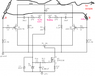
when you are measuring input voltage - you must place probes between positive and negative points of input ; in this case they are + input and - input , and you must disregard ground . input is two pole , not 3 or 3,5 pole
when measuring output , you also must put probes between positive and negative points of output ; in this case they are ground and negative output ; disregard positive output .
am I guessed right?
Zen Mod said:
so - then is mistake in your measuring approach ;
when you are measuring input voltage - you must place probes between positive and negative points of input ; in this case they are + input and - input , and you must disregard ground . input is two pole , not 3 or 3,5 pole
when measuring output , you also must put probes between positive and negative points of output ; in this case they are ground and negative output ; disregard positive output .
am I guessed right?
My scope only has one probe. It is a dual input scope, though. So, I'm not sure what you mean when you say probes (plural).
I checked the voltage amp feeding the x-over; it reads matching voltages on both outputs. The x-over, itself, gives a mismatch in output voltages.
I must need a new x-over? Several days ago I ordered 25 pcs. TL072 op-amps in order to play with ESP's electronic x-over design. Nice thing about DIY: when things break, you can always study and build new components yourself! 😀 😀 😀
I have a little alligator clip hanging from my probe tip. Is this the negative probe you speak of?
I'm quite the nube when it comes to scopes.
I'm quite the nube when it comes to scopes.
carpenter said:I have a little alligator clip hanging from my probe tip. Is this the negative probe you speak of?
I'm quite the nube when it comes to scopes.
yes ;
tip is hot, alligator clip is neg side of probe .............. on both pics abobe - aligator clip is on "B"
http://www.bcae1.com/oscope.htm
and - for mucho other things - go to the root of site :
http://www.bcae1.com/
Zen Mod said:
yes ;
tip is hot, alligator clip is neg side of probe .............. on both pics abobe - aligator clip is on "B"
http://www.bcae1.com/oscope.htm
and - for mucho other things - go to the root of site :
http://www.bcae1.com/
Choky, you're a little dream-boat. 😀 I always learn something new when you're around.
carpenter said:
Choky, you're a little dream-boat. 😀 I always learn something new when you're around.
I'm your Nanny
Magura is pooftah ......... ( I hope his Missus doesn't read this thread )

Zen Mod said:
I'm your Nanny
Magura is pooftah ......... ( I hope his Missus doesn't read this thread )
pooftah fag gay faggot fairy homosexual poof queer
1. pooftah 19 up, 2 down
a homosexual man (England, Australia)
Elton John is a pooftah.
Choky, you're very, very bad.

 You've probably gonna burn in hell for that one.😀
- Home
- Amplifiers
- Pass Labs
- JfetBOZ mods